14
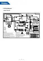
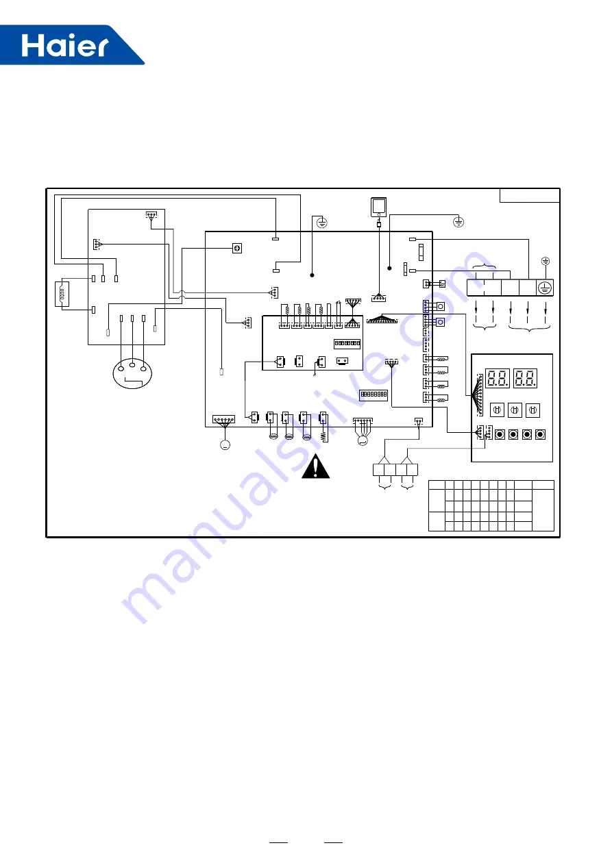
8. Wiring Diagram
CN37
CN34
T25A/250VAC
FUSE1
CN13
CN15
CN9
R
BL
W
U
Compressor
R
V
B
W
Y/G
Y
/
G
Inverter module
Reactor
AC-L
AC-N
U
W V
BL CN10
BL
R
W
N
P
CN19
CN27
B CN11
N-OUT
L-OUT
AC-N
PE
HPS
AC-L
CN35
PE
Y
/
G
BL
R
CN1
R
CN29
CN28
BL
R
CN23
CN4
B
TE(1)
CN6
CN7
TAO
TS
W
B
W
R
CN21
Power supply
BM1
N
O
1 2 3 4 5 6 7 8
CN16 CN17 CN25
HEATER
4WV
G
Y
W
CN12
DC-FAN
W
M
BL CN33
W CN10
LO
LI
INV-POWER
W
CN51
【
Electrical wiring diagram
】
W
CN30
Main board
[1] [2] [3] [4] [5] [6] [7] [8]
0 1 0 0 1 0
BM1
BM
Model
【BM Indication】
0 0
1
0
100
0 means
OFF,
1 means
ON
82
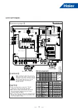
【WARNING】
Before checking the inside of the control box,
please turn off the power supply and keep the
unit closed for more than 10 minutes to ensure
that the voltage between P and N on the
converter board has been reduced to
less than DC 20V.
P
CN3
Td1
R
CN5
W
B
W
B
W
W
CN41
BL
CN18
R
COM
R
CN11
THO
TW I
TH I
TWO
W
CN45
BL
CN59
W
CN43
Y
CN44
W
CN47
BL
CN53
Y
CN58
BL
CN57
B
CN56
R
CN40
N
L
Wire controller
Docking connector
Water
board
LEVA1
M
R
CN8
SV1
SV2
1
0
0
MODE
BM2
N
O
1 2 3 4 5 6 7 8
0 0 0
BM2
0
1
82
100
0
1
0 0 0 0 0 0
0 0 0
1 0
0
Remarks
W
CN1
SMG1
SMG2
SW4 SW5 SW6 SW7
UP DOWN EXIT ENTER
W
CN2_1
W
CN2
Display board
L
N
W
CN24
P
OUT I/O
A
Q
Centralized
controller
B
Inside pump
Connect to Terminal block PUMP
Connect to water
board CN57
0150531727
PUMP
T3.15A/250
VAC
FUSE2
Colours:
B : Black
BL: Blue
Y : Yellow
G : Green
R : Red
W: White
WS
G
CN46
Ps
Pd
【
NOTES
】
·Please check the power firstly before test , and make
sure the crankcase heater power on for 12 hours
at least to protect compressor.
·Forbid connecting the power wire to the “P,Q,A,B” ,
otherwise the control board will be damaged.
·Please connect the wire controller to the docking terminal,
and then fix the back side of the docking terminal with a
wire clamp to prevent pulling.
SW1
SW2
SW3
AU082FYCRA(HW)
Summary of Contents for AU082FYCRA(HW)
Page 1: ...ATW Service Manual SYJS 03 2019REV A Edition 2019 03 ...
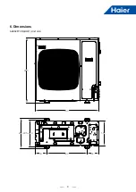
Page 11: ...9 405 410 600 174 174 450 950 965 395 6 Dimensions AU082FYCRA HW Unit mm ...
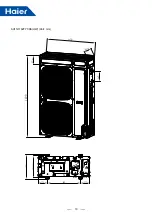
Page 12: ...10 AU112 162FYCRA HW Unit mm 1490 950 380 187 405 410 600 174 174 450 170 ...
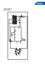
Page 13: ...11 AU082FYCRA HW 7 Piping Diagram ...
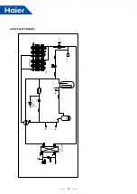
Page 14: ...12 AU112 162FYCRA HW ...
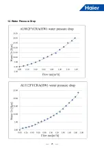
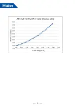
Page 27: ...25 12 Water Pressure Drop ...
Page 28: ...26 ...

