GV-395 Virtex-II DSP Hardware Accelerator Manual
GV & Associates, Inc.
07/10/04
6
2.0
GVA-395 Power Configuration
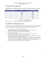
The GVA-395 Hardware Accelerator was delivered with Molex power connector. Care should be taken to insure
that the proper power levels are applied to this power connector. The power configuration is shown in Table 2.1.1.
Power Connector Pin No.
Power
Connector Wire Color
1 Ground
Black
2 Ground
Black
3 Ground
Black
4 Ground
Black
5 +5V Red
6 +5V Red
7 +5V Red
8 +5V Red
2.1.1
GVA-395 Power Configuration Table
The GVA-395 Hardware Accelerator comes configured for a single supply mode (+5V).
3.0
Initial GVA-395 Diagnostic Check-out
In order to verify proper operation of the GVA-395, the customer should perform the following tests upon receipt of
the unit. The GVA-395 on-board Flash EEPROM when delivered is configured with the diagnostic program for all
of the tests. Additionally, the GVA-395 is setup to configure the FPGAs for the diagnostic routine.
1.
Insure that a jumper block is on the jumper block at JP5 and JP9.
2.
Connect the power cable to at least a 3 A +5V regulated power supply as describe in Section 2.0.
3.
Attach a 34-wire ribbon cable to J1 and J2 for the LVDS loop back test.
4.
Attach a 34-wire ribbon cable to J4 and J5 for the LVTTL loop back test.
5.
Apply power to the GVA-395.
6.
Verify that the proper voltages are present: +5V->TP8, +3.3V->TP9, +2.5V->TP10, 1.5V->TP11.
7.
The LEDS of AR3 will toggle while the FPGA are being programmed
8.
Once the tests which are described in Section 16 are run, all of the LEDs (D1 thru D40) should be lite. This
indicates that the tests have been successfully completed.
9.
Using a function generator, an analog signal should be connected to P1 thru P4. The same waveform may
then be viewed with either an oscilloscope or spectrum analyzer at P7 thru P10. It should be noted that the
customer should use an anti-aliasing filter such as SLP-30 (Mini-Circuits) on each input channel and a
similar smoothing filter on each output channel. Without the filters, excessive noise may be present.
10.
The diagnostic tests may be re-initiated by pressing the reset button SW1.


