


GST-IFP8 Intelligent Fire Alarm Control Panel
Installation and Operation Manual
Page 9
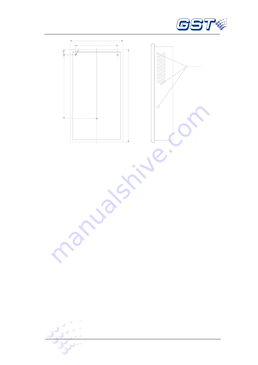
Wiring Hole
583mm
388mm
480mm
850mm
Fig. 4-1
4.3 Start-up Check
After installation, apply power to the FACP as shown in Fig. 4-2a. Connect the battery
plug onto the power board, and then turn on the mains switch in the cabinet and check if
the FACP can self-test. The procedures are as follows.
Check if the LCD showing system messages such as fire alarm is illuminated.
Check if the LEDs showing the state of system can be illuminated one by one.
Check if the LEDs showing the device state in zone indication panel are illuminated
in turn.
Check if the buzzer can give loud alarm sounds.
4.4 External Connection
4.4.1 Mains Connection
GST-IFP8 Fire Alarm Control Panel receives power from a 220VAC/230VAC
,
50Hz/60Hz supply.
The incoming power feed cable Earth (Green/Yellow) wire should be connected to
the earth terminal.
Connect the live wire to terminal L and the neutral wire to terminal N.
Note: Do not power the system until the installation is completed.
Summary of Contents for GST-IFP8
Page 1: ......