


G0620 Main Control Panel
-7-
Blade Tilt
Adjustments
The blade tilt can be adjusted manually or auto-
matically with numerical input. The adjustment
can be cancelled at any time by pressing the Stop
key.
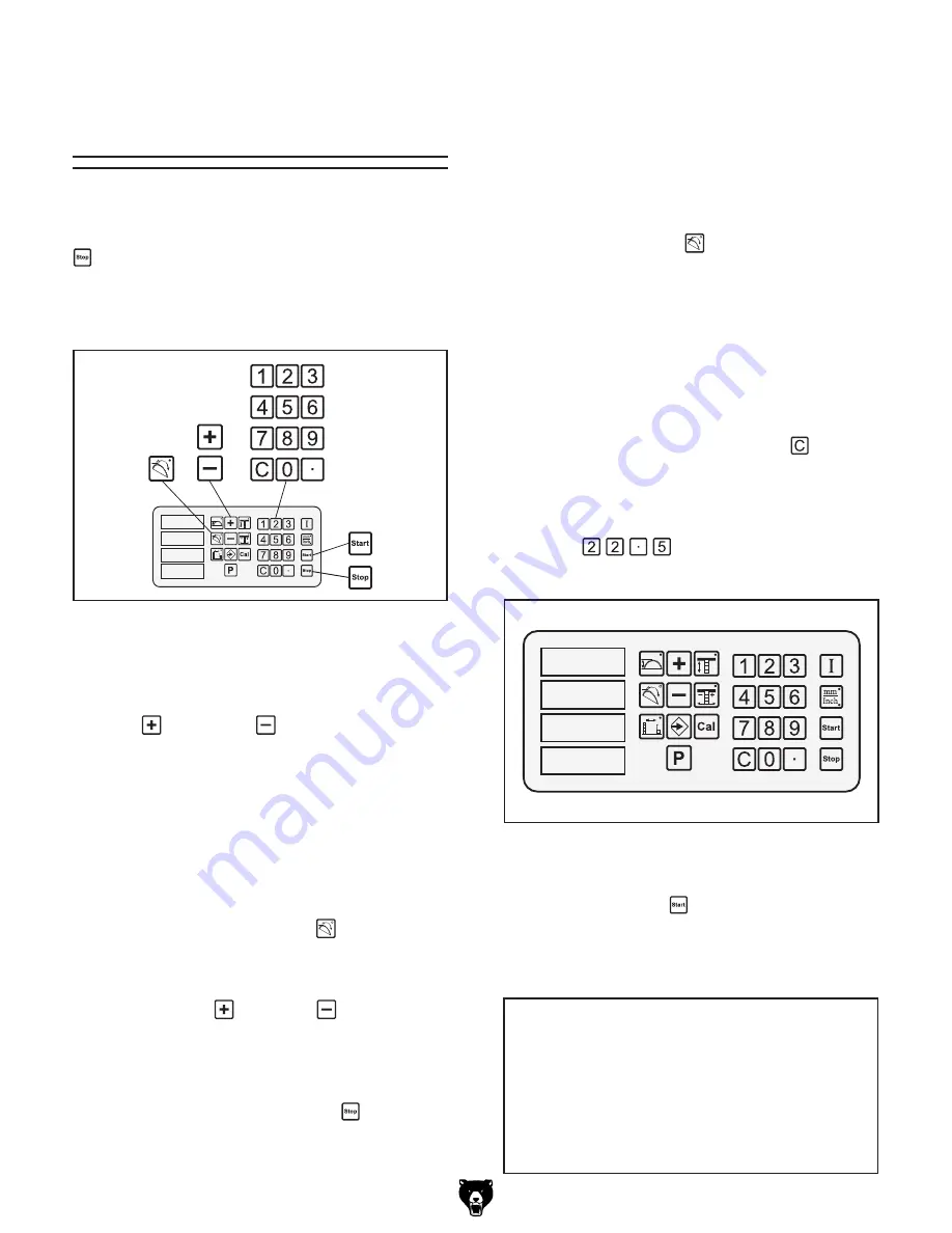
Figure 8
shows the keys used during the blade tilt
adjustment procedures in this section.
Numerically Adjusting Blade Tilt
You can enter a desired angle with the number
keys and the blade will automatically adjust to that
angle.
To adjust the blade tilt automatically with
numerical input:
1.
Press the blade tilt key.
The indicator light on the key shines to tell
you that the control panel is ready to accept
your input.
2.
Enter the desired blade tilt with the number
keys. As you press the keys, the display will
flash the numbers you have entered. If you
press a wrong number or make a mistake
with your input, press the clear
key and
start over.
Example:
If you want the blade tilt to be
22.5", then you would press the following
keys:
, and the display would look
similar to
Figure 9
.
����
����
�
����
Figure 9.
Example of 22.5° entered into blade tilt
display.
3.
Press the Start
key. The control panel
accepts your input, moves the blade to your
desired tilt, and the indicator light on the
blade tilt key stops shining.
Manually Adjusting Blade Tilt
The blade tilt can be manually adjusted using
the plus
and minus
keys. In some cases,
manual adjustments can save time by eliminating
measurements. For example, if you want to adjust
the blade tilt to match an existing mitered cut, you
can place the workpiece next to the blade and
use the manual controls to adjust the blade tilt as
desired.
To adjust the blade tilt manually:
1.
Press the blade tilt control
key. The indi-
cator light on the key shines to show that the
control panel is ready to accept input.
2.
Use the plus
or minus
key to manu-
ally position the blade tilt. (Bump the keys for
small adjustments and hold the keys down for
large adjustments.)
3.
When finished, press the Stop key, so the
indicator light stops shining.
�
�
�
����
Figure 8
. Keys used in blade tilt adjustment
procedures.
NOTICE
Changes to the blade tilt affect blade height.
After performing Step 3, the blade height
will be different than shown in Figure 9. To
save time of having to re-enter the blade
height, enter the blade tilt before entering
blade height.


