


G0620 Main Control Panel
-19-
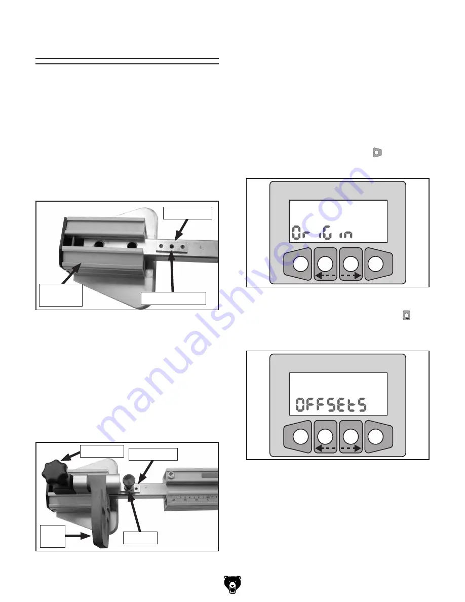
Using Offsets
The crosscut fence includes three origin blocks
located inside the channel where the stop blocks
slide in the fence.
The origin block closest to the blade is the "Home"
origin block for the digital stop, which is always
used in conjunction with the other two origin
blocks when the second stop block is used. Using
the second stop block with the origin blocks is the
only way to get a digital reading with the second
stop, and hence, when using the fence extension
(
Figure 36
).
���
������� �������
�
�����
���
Figure 38.
Origin screen.
2.
Press the right arrow key (mm/inch
�������
key)
twice until the display shows the word
"Offsets" as in
Figure 39
.
���
������� �������
�
�����
���
Figure 39.
Offsets screen
It works like this: the stopper in the digital stop
block is dropped into the home origin block. This
locks the digital stop block to the sliding plate
inside the fence. The second stop block is then
moved to one of the two origin blocks and locked
using a similar stopper (
Figure 37
). The display
on the digital stop block is then changed to one of
the "ORG" settings, resulting in the display read-
ing the position of the second stop block, rather
than the position of the digital stop block.
Figure 36.
Origin block near fence extension.
Origin Block
Hole for Stopper
Fence
Extension
Figure 37.
Second stop block engaged in origin
block near fence extension.
Origin Block
Stopper
Lock Knob
Basically, the display shows the dimension of the
second stop block because it adds a pre-pro-
grammed offset distance from one origin block to
the other.
Aside from the two origin block offsets, two addi-
tional offsets can be programmed in the controller
to be used with jigs or measurement blocks.
Entering Offset Values
1.
Press and hold the F/ENTER
�
�����
key until the
"Origin" screen appears as in
Figure 38
.
Stop
Block


