


-4-
G0620 Main Control Panel
Quick Start
Manual Adjustments
The components controlled by the keys in
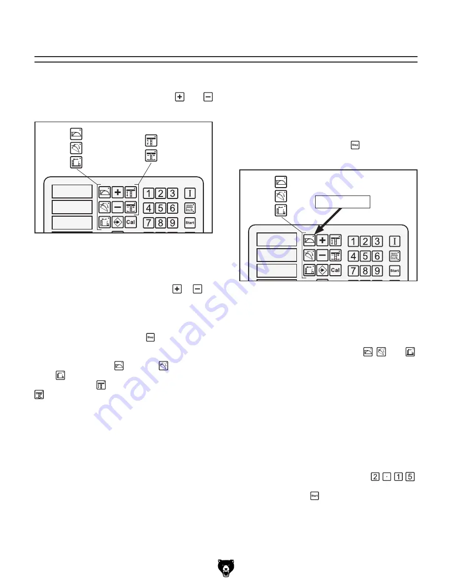
Figure
2
can be manually adjusted using the
and
keys.
�
�
�
����
Figure 2.
Controls keys capable of manual
operation.
To manually adjust any of these components,
press one of the control keys shown in
Figure 2
so its indicator light shines, then press or as
desired to manually position the related control.
When finished, press the control key again so its
indicator light stops shining.
Note:
You can press the Stop
key at any time
to cancel the operation.
Only the blade height , table tilt , and cutting
width controls allow numerical input. The scor-
ing blade height
and scoring blade alignment
controls must be adjusted by eye or by an
independent guide, such as a straightedge.
Typically manual controls are used when math-
ematical adjustments are not practical, such as
those adjustments done by eye or when setting
the components to a marked workpiece.
Numerical Input Adjustments
The components controlled by the keys in
Figure
3
can be controlled by numerical input and
will automatically adjust to the dimension you
entered. For more details on controlling any one
component, refer to the
Section 3: Operations
.
Note:
You can press the Stop
key at any time
to cancel the operation.
�
�
�
����
Figure 3.
Controls capable of being moved by
numerical input.
To move the components with numerical
input:
1.
Press the desired control key ( , , and )
for the component that you want to move.
The indicator light on the key (
Figure 3
)
shines to tell you that the control panel is
ready to accept your input.
2.
Enter your input with the number keypad.
As you press the keys, the display will flash
the numbers you have entered.
Example:
If your input is 2.15", then you
would press the following keys: .
3.
Press the Start key and the component will
move to where it is directed by your input.
Indicator Light


