


-14-
G0620 Main Control Panel
Rip Fence Cutting
Width Calibration
Performing this procedure ensures that cutting
width from the rip fence accurately matches what
is shown in the digital display.
We recommend calibrating the blade height every
time you change the blade.
The calibration is a simple procedure that only
takes minutes. For precise results, use a pair of
calipers to take the measurements noted below.
Note:
You can stop the calibration process at any
time by pressing the Stop key.
Tools Needed
Qty
Calipers (Dial or Digital) .................................... 1
To calibrate the rip fence cutting width:
1.
Raise the blade up to 2.25" high, tilt the blade
to 0.0, and move the rip fence 4" away from
the blade.
2.
Measure the distance from the blade to the
fence by either making a test cut and measur-
ing the result or by using a pair of calipers.
—If using a test cut to measure this dis-
tance, make the test cut, measure your cut
workpiece, then proceed to
Step 7
.
—If using calipers to make your measure-
ment, proceed to
Step 3
.
3.
Completely close your calipers and make
sure they are at 0.000" (if not, zero them
now).
4.
DISCONNECT SAW FROM POWER!
5.
Close the calipers on one of the carbide teeth
on the main blade, then zero the calipers out.
(This will automatically subtract the blade
thickness when measuring the cutting width
in the next step.)
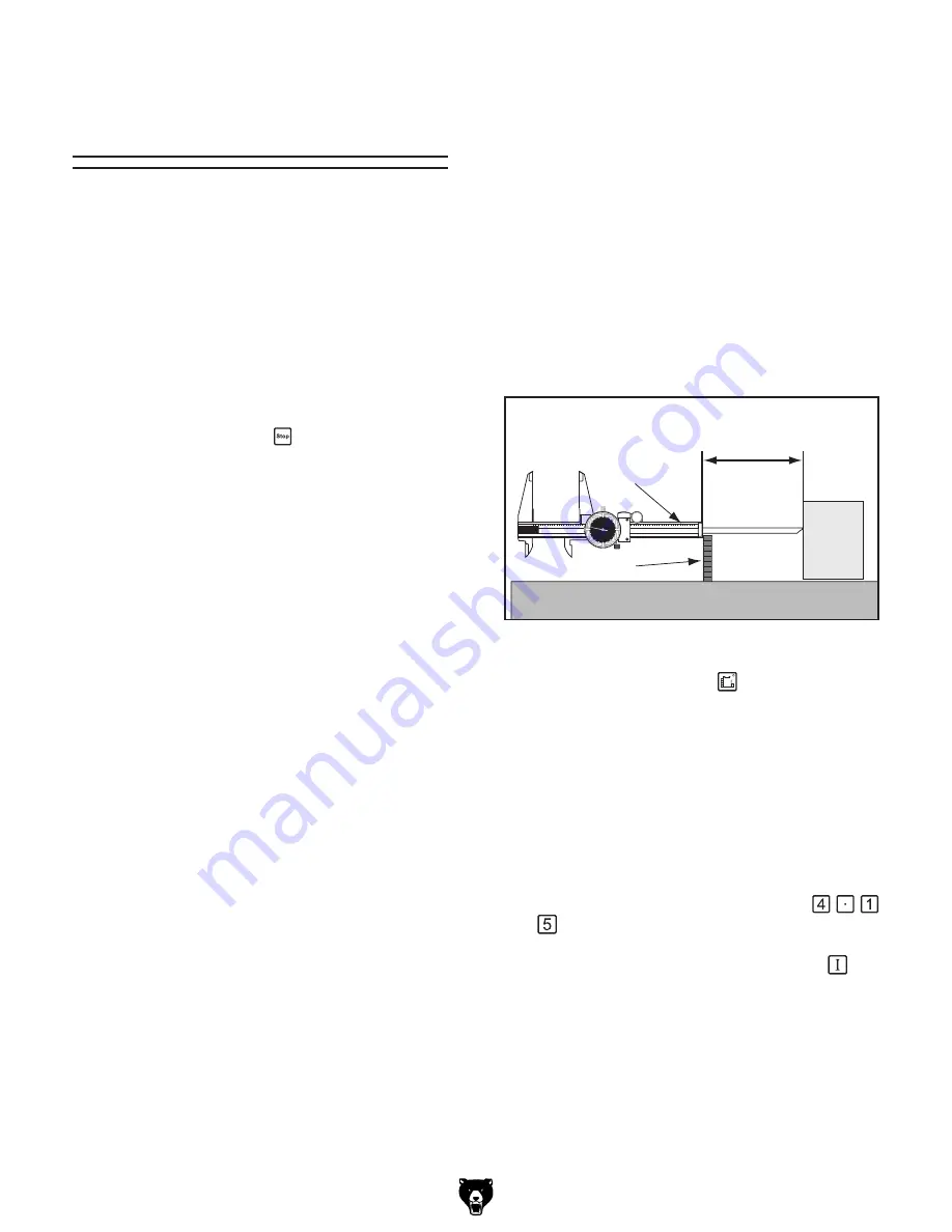
6.
Place the bottom of the calipers on one of
the carbide teeth and extend the caliper mea-
surement bar to touch the rip fence, as shown
in
Figure 26
, then lock the calipers in place
and read the measurement.
—If the measurement on the calipers reads
0.02" or less away from 4", then the rip
fence cutting width calibration is already
correct.
—If the measurement on the calipers reads
more than 0.02" away from 4", then the rip
fence cutting width must be recalibrated.
Continue to the next step.
�
�
��
��
��
��
��
��
��
��
��
�����
��������
��������������
�����������������������
�����
�����
Figure 26.
Measuring cutting width with calipers.
7.
Press the cutting width
key. The indicator
light on the key shines to show that the con-
trol panel is ready to accept input.
8.
Enter your measurement from
Step 5
with
the keypad.
As you press the keys, the display will flash
the numbers you have entered.
For Example:
If you measured 4.15", then
you would press the following keys:
.
9.
Press and hold the input confirmation
key
until the display stops flashing. The new set-
ting now remains on the display.


