Grizzly G0620 Supplement Manual Download Page 22

-20-

G0620 Main Control Panel

3. 

Press the F/ENTER 

�����

 key. 


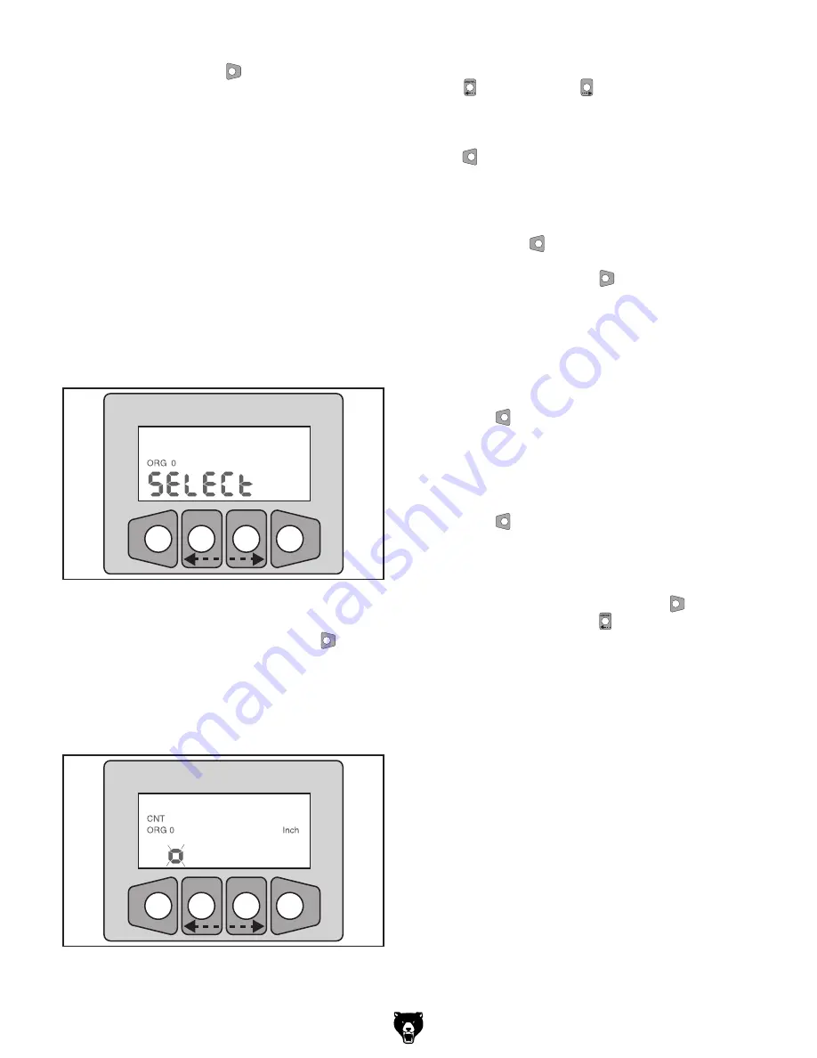
"Select" appears on the display (

Figure 40

with "ORG" and a number next to it, prompt-
ing you to select which ORG to program.


Note: 

When  programming  "ORG  0,"  put  the 

digital stop block stopper in the home origin 
block (the closest one to the blade) and put 
the  second  stop  block  stopper  in  the  ori-
gin  block  closest  to  the  home  origin  block. 
Measure  the  distance  from  the  usable  face 
of  the  digital  stop  block  to  the  usable  face 
of  the  second  stop  block,  and  program  that 
distance  into  the  controller.  When  program-
ming "ORG 1," move the second stop block to 
the origin block near the fence extension and 
repeat.

���

������� �������

�����

���

Figure 40.

 ORG select screen.

4.

  Use the arrow keys to select which ORG to 

program, then press the F/ENTER 

�����

 key.


The display changes to an entry screen with 
a  flashing  "0",  as  shown  in 

Figure  41

.  (Due 

to  resolution  settings,  the  number  of  zeros 
displayed may not match the figure exactly.)

���

������� �������

�����

���

��������

Figure 41.

 Controller ready to enter a value for 

ORG 0.

5.

  Use the left and right arrows on the ABS/REL  

  and  mm/inch 

�������

  keys  to  select  the  digit 

you want to modify. 


Modify  the  digits  by  pressing  the  CLR/SET 

���

���

 key when the desired digit is blinking.


The smaller 0 at the far left of the number rep-
resents a positive value, but can be modified 
to a negative value if desired by pressing the  
CLR/SET 

���

���

 key when it is blinking.

6.

  Press the F/ENTER 

�����

 key to save the cur-

rent number in the controller. 


The  display  will  go  back  to  the  "Select" 
screen. From this screen, you can enter addi-
tional cutoff values by repeating 

Steps 4-5

.

7.

  To  exit  the  "Select"  screen,  press  the  CLR/

SET 

���

���

 key.


The  display  will  go  back  to  the  "Offsets" 
screen.

8.

  To exit the "Offsets" screen, press the CLR/

SET 

���

���

 key.

Activating Stored Offsets

1.

  Press  and  hold  the  F/ENTER 

�����

  key,  then 

press  the  ABS/REL    key  to  cycle  through 
the ORG numbers.


The  offset  value  is  automatically  applied  to 
the current value displayed when the related 
ORG number is selected.

Summary of Contents for G0620

Page 1: ...CONTROLS COPYRIGHT MARCH 2008 BY GRIZZLY INDUSTRIAL INC WARNING NO PORTION OF THIS MANUAL MAY BE REPRODUCED IN ANY SHAPE OR FORM WITHOUT THE WRITTEN APPROVAL OF GRIZZLY INDUSTRIAL INC TR10571 PRINTED...

Page 2: ......

Page 3: ...de Tilt Adjustments 7 Rip Fence Adjustments 8 Combining Adjustment Entries 9 Memory Functions 10 Blade Diameter Calibration 11 Blade Height Calibration 12 Blade Tilt Calibration 13 Rip Fence Cutting W...

Page 4: ...to Grizzly s policy of continuous improvement changes may be made at any time with no obligation on the part of Grizzly For your convenience we always keep current Grizzly manuals available on our we...

Page 5: ...ring Blade Height Key G Number Keys H Input Confirmation Key I Millimeter Inch Selection Key J Start Key K Stop Key L Decimal Key M Clear Key N Function Confirmation Key O Memory Set Key P Pre Saved M...

Page 6: ...ts are not practical such as those adjustments done by eye or when setting the components to a marked workpiece Numerical Input Adjustments The components controlled by the keys in Figure 3 can be con...

Page 7: ...on Figure 5 Scoring blade controls keys Scoring Blade Height 1 Press the scoring blade height control key The indicator light on the key shines to show the selected control is active 2 Use the plus an...

Page 8: ...and the display would look similar to Figure 7 Note It may be necessary to enter a zero first if your numerical input is less than one Figure 7 Example of 2 25 entered into blade height display 3 Pre...

Page 9: ...de tilt display 3 Press the Start key The control panel accepts your input moves the blade to your desired tilt and the indicator light on the blade tilt key stops shining Manually Adjusting Blade Til...

Page 10: ...isplay would look similar to Figure 11 Figure 11 Example of 18 25 entered into rip fence cutting width display 3 Press the Start key The control panel accepts your input moves the rip fence to the des...

Page 11: ...anel is ready to accept input 2 Use the number keys to enter the blade height Figure 12 Figure 12 First entry Figure 13 Second entry Figure 14 Third entry 3 Press the blade tilt key The indicator ligh...

Page 12: ...tween 1 and 29 to repre sent this saved setting Figure 17 The number 22 programmed to save the currently shown dimensions 4 Press and hold the input confirmation key until the display stops flashing T...

Page 13: ...bration The exact dimensions of a blade can be pro grammed into the control panel so the blade height controls will not be skewed by blades of different sizes We recommend performing this calibration...

Page 14: ...the control panel and compare that to your measurement If the blade height displayed is the same as your measurement then the blade height calibration is already correct If the displayed blade height...

Page 15: ...hen the blade tilt calibration is already correct If the square does not fit flat against the blade you can see a gap between the square and the blade then continue to the next step to calibrate the b...

Page 16: ...are at 0 000 if not zero them now 4 DISCONNECT SAW FROM POWER 5 Close the calipers on one of the carbide teeth on the main blade then zero the calipers out This will automatically subtract the blade...

Page 17: ...if a sacrificial fence is attached to the standard rip fence Figure 27 Fence position A Figure 28 Fence position B To calibrate the rip fence thickness 1 Turn the control panel OFF 2 Push and hold the...

Page 18: ...Gap Sign G Function Key Activated Sign H Current Relative Counter Number I Current Absolute Counter Number Memory Slots for Storing Offsets J Diameter Function K Relative Measuring Mode L Millimeter U...

Page 19: ...layed The display will automatically exit out of the battery charge screen after two seconds Changing Resolution The display can be adjusted to show a resolu tion or accuracy from one to four decimal...

Page 20: ...to save the cur rent number in the controller as the cali brated measurement The controller is now calibrated to be accurate from the flip stop to the saw blade If the calibrated distance is shown on...

Page 21: ...ital stop block to the sliding plate inside the fence The second stop block is then moved to one of the two origin blocks and locked using a similar stopper Figure 37 The display on the digital stop b...

Page 22: ...ings the number of zeros displayed may not match the figure exactly Figure 41 Controller ready to enter a value for ORG 0 5 Use the left and right arrows on the ABS REL and mm inch keys to select the...

Page 23: ......

Page 24: ......

Reviews: