


G0620 Main Control Panel
-3-
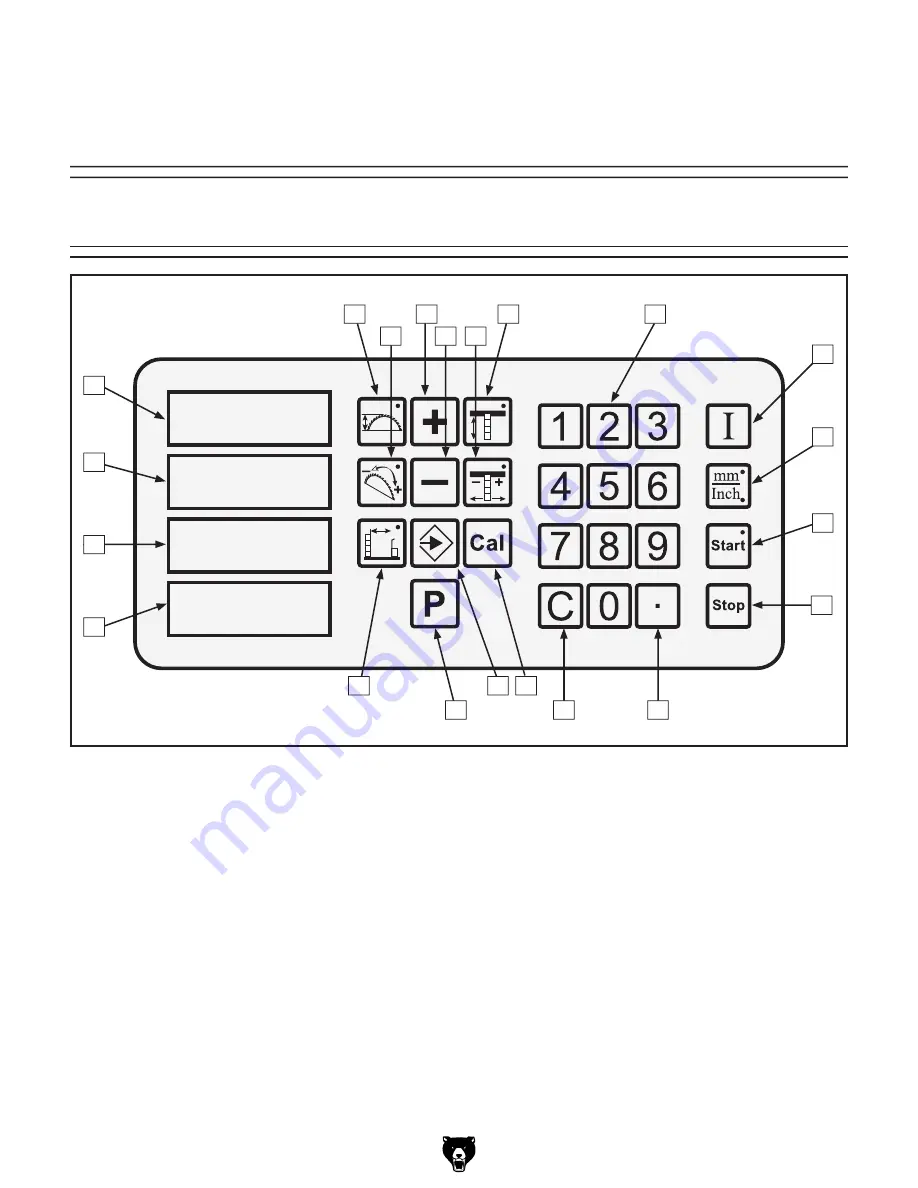
Figure 1.
Control panel identification.
Control Panel Identification
A.
Blade Height Key
B.
Blade Tilt Key
C.
Manual Increase Key
D.
Manual Decrease Key
E.
Scoring Blade Alignment Key
F.
Scoring Blade Height Key
G.
Number Keys
H.
Input Confirmation Key
I.
Millimeter/Inch Selection Key
J.
Start Key
K.
Stop Key
L.
Decimal Key
M.
Clear Key
N.
Function Confirmation Key
O.
Memory Set Key
P.
Pre-Saved Memory Recall Key
Q.
Cutting Width Key
R.
Memory Set and Speed Display
S.
Cutting Width Display
T.
Blade Angle Display
U.
Blade Height Display
�
�
�
����
C
F
G
H
I
J
K
M
O
P
Q
R
S
T
A
U
N
L
D
B
E
MAIN CONTROL PANEL
OPERATIONS


