


G0620 Main Control Panel
-11-
����
���
�����
�
�����
��
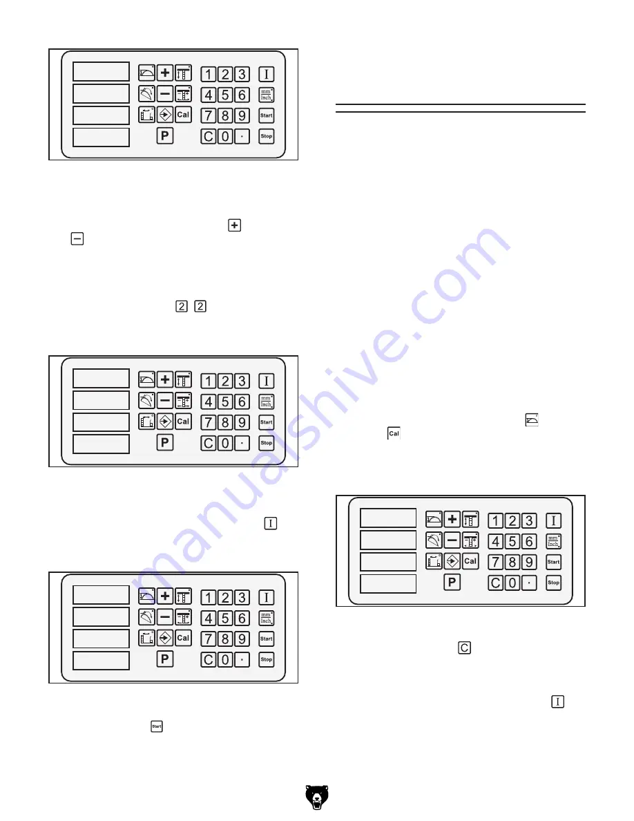
Figure 19.
"P" displayed on control panel to
indicate system is ready to recall saved settings.
2.
Type in the number of the saved setting you
want to recall, or use the plus
and minus
keys to scroll through each saved setting
to find the one you want.
Example:
To recall the setting saved in the
example of the previous subsection, press
the following keys:
. The display will
look similar to
Figure 20
, showing the dimen-
sions of each of the three components.
����
����
�����
�
�����
��
Figure 20.
Saved setting 22 entered into the
recall display.
4.
Press and hold the input confirmation
key
until the dimensions start flashing, as shown
in
Figure 21
.
����
����
�����
����
Figure 21.
Recalled dimensions flashing.
5.
Press the Start key.
All components will move to their respective
positions
Blade Diameter
Calibration
The exact dimensions of a blade can be pro-
grammed into the control panel, so the blade
height controls will not be skewed by blades of
different sizes. We recommend performing this
calibration procedure every time you change
blades, especially if changing between 12" and
14" blades.
Tools Needed
Qty
Measuring Tape ................................................ 1
To calibrate the control panel for your exact
blade diameter:
1.
DISCONNECT SAW FROM POWER.
2.
Remove blade, measure its diameter, then
reinstall it.
3.
Connect saw to power, reset stop button, turn
ON
the control panel, then turn it
OFF
.
4.
Press and hold the blade height
and cali-
brate keys at the same time, then turn the
control panel back
ON
. After a few seconds,
the current blade diameter will flash and the
display will look similar to
Figure 22
.
5.
Press the clear key , then type in the exact
dimensions of your blade with the number
keys.
6.
Press and hold the input confirmation
key
until the display changes to the normal view.
�����
Figure 22.
Blade diameter display.


