GMV DC Inverter VRF
60
——
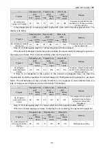
Debugging code
Progress code
Status code
Meaning
Progress
LED1
LED2
LED3
Code
Display
status
Code
Display
status
Code Display status
06_outdoor unit's
parts inspection
db
ON
06
ON
OC
ON
The system detected that
there's no fault for outdoor
unit's parts. Then it will
automatically enter into
the next step.
If an abnormality is detected, it will stay in the current state and manual troubleshooting is
required. The corresponding faults are as below:
——
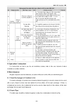
Debugging code
Progress code
Status code
Meaning
Progress
LED1
LED2
LED3
Code
Display
status
Code
Display
status
Code
Display
status
06_outdoor unit's
parts inspection
db
ON
06
ON
Corresponding
error code
ON
The system detected that
there's fault for outdoor
unit's parts.
Refer to the part of “Troubleshooting” for the corresponding troubleshooting method.
Step 10: The unit debugging step 07 is “indoor unit's parts inspection”.
If there is no abnormality in the detection, the display is as below, and then it automatically enters
the next step of detection.
——
Debugging code
Progress code
Status code
Meaning
Progress
LED1
LED2
LED3
Code
Display
status
Code
Display
status
Code
Display
status
07_indoor unit's
parts inspection
db
ON
07
ON
OC
ON
The system detected
that there's no fault for
indoor unit's parts. Then
it will automatically enter
into the next step.
If an abnormality is detected, it will stay in the current state and manual troubleshooting is
required. The corresponding faults are as below:
——
Debugging code
Progress code
Status code
Meaning
Progress
LED1
LED2
LED3
Display
status
Code
Display
status
Code
Display
status
Display
status
07_indoor unit's parts
inspection
db
ON
07
ON
XXXX/
correspodin
g error code
ON
The system detected that
there's fault for indoor
unit's parts.
XXXX indicates the engineering no. of fault indoor unit. 3s later, the corresponding error code will
be displayed. For example, if d5 fault occurs for No.100 indoor unit, LED3 displays as below: 01 (2s
later) 00(2s later) d5, and they will display like that circularly.
Refer to the part of “Troubleshooting” for the corresponding troubleshooting method.
Step 11: The debugging step 08 is “compressor preheat confirmation”.
If the preheat time has reached for 2h, the display is as below. Then it will enter into the next step
for inspection.


