❏
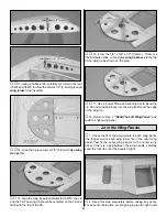
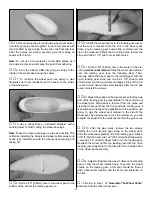
4. Thread a nylon clevis approximately 14 turns onto one
end of each pushrod. Remove the backing plate from two
large nylon control horns and connect the horns to the
clevises in the outer hole.
❏
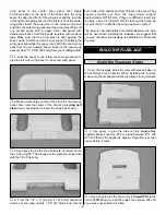
5. Temporarily install the rudder and elevator on the
plane. Insert the pushrods into the outer pushrod tubes.
Position the control horns on the elevator and rudder as
shown on the plans. Mark the location of the control horn
mounting holes and drill 3/32" [2.4mm] holes at the marks.
Temporarily mount the control horns to the elevator and
rudder with the backing plates and 2-56 x 1/2" machine screws.
❏
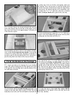
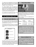
6. Mount the receiver switch on the side of the fuse,
opposite the engine exhaust. We use a Great Planes Switch
& Charge Jack Mounting Set (GPMM1000) (not included)
on all of our planes. This allows you to check and charge the
receiver battery without removing the wing.
❏
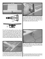
7. Wrap the receiver and receiver battery in 1/4" foam
rubber (not included).
❏
8. Temporarily position the receiver and receiver battery
on the fuse bottom. Later, the receiver battery may be
moved forward or aft to balance the plane. Plug the receiver
battery into the receiver switch. Later, after the location for
the receiver battery and receiver have been determined,
use sticks to hold them in position so that they cannot shift
in flight.
❏
9. Drill 1/16" [1.6mm] pilot holes and mount the elevator,
rudder and throttle servos, using the hardware that came
with your radio. When mounting the elevator and rudder
servos, align the servo arms with the elevator and rudder
pushrods.
❏
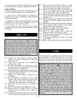
10. With the servos centered and the control surfaces in
the neutral position, use a felt-tip pen to mark where the
elevator and rudder pushrods cross the mounting holes in
the servo arms. Note: The servo arms have been painted
for clarity.
❏
11. Disconnect the clevises from the control horns. Make
a 90° bend at the marks you made. Temporarily install a
34
Summary of Contents for Old Timer
Page 6: ...6 DIE PATTERNS...
Page 7: ...7 DIE PATTERNS...
Page 44: ...TWO VIEW DRAWING Use copies of this page to plan your trim scheme...
Page 45: ...B C...
Page 46: ...D A...

