CS610-UM-251-9370
8-12
8. DISASSEMBLING AND ADJUSTING THE MECHANICAL PARTS
8.9 Drive Belt
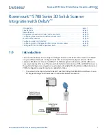
Detaching the drive belt
(1) Detach the left side cover (see Section 8.2).
(2) Loosen the two M4L6 binding head screws holding the motor.
(3) Detach the drive belt from the pulleys.
Belt
M4L6 binding
head screws
Reattaching the drive belt
(1) Reattach the drive belt by reversing the sequence of steps in which it was detached.
(2) Install the belt to the 180-degree punched markings of the drive roller shaft as shown below.
Adjust the punched
holes by 180 degrees.
(3) Adjust the drive belt tension.
Summary of Contents for CS610-11eN
Page 1: ...COLORIMAGESCANNER SERVICE MANUAL CS610 SERIES CS610 UM251 02 9370...
Page 2: ......
Page 42: ......
Page 44: ......
Page 118: ......
Page 120: ......
Page 128: ...13 PARTS LIST CS610 UM 251 9370 13 8 CIS Unit 6 4 2 11 9 10 12 8 1 3 5 7...