


Pag. 15
Once the gas conversion operations have been completed, check the dismantled parts for leaks using soapy
water or foam products. DO NOT SEARCH FOR LEAKS WITH NAKED LIGHTS.
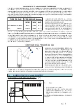
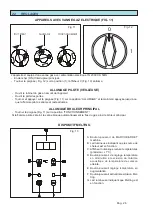
REPLACING THE PILOT BURNER NOZZLE (Fig. 8)
- Unscrew screwed-on cap (Ref. 1), remove the
nozzle (Ref. 2) and replace it with one that is
suitable for the type of selected gas.
- Refit the screwed-on cap.
- Use a foam product to check that the cap
does not leak.
After converting or adapting for the gas, the
plate specifying the type of nozzles used MUST
be affixed above the rating plate.
Fig. 8
�
�
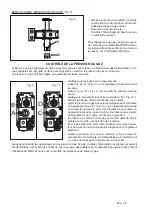
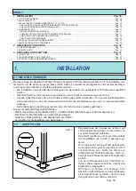
• check that the nozzles are the right ones;
• remove screw “A” (Fig. 9) on the pressure outlet of the valve;
• remove screw “B” (Fig. 9) on the pressure control of the val-
ve;
• apply the pressure gauge to the pressure outlet “D” (Fig. 10);
• switch on the fryer and light the burners;
• regulate the gas pressure to the settings given in the chart by
turning the screw “C” (Fig. 10); remember that by turning the
screw clockwise, the pressure is increased and by turning it
anti-clockwise the pressure is reduced.
• for the G20 version, the output pressure of the valve must be
9,5 mbar;
• for liquid petroleum gas (LPG) (G30-G31) turn the screw to max
(valve control bypassed, pressure controlled by an external
control device);
• when the pressure is at the correct level, switch off the fryer,
remove the pressure gauge and replace the fixing screws;
check that there are no leaks using the special liquid for that
purpose.
Fig. 10
CHECKING GAS PRESSURE
Check that the installed nozzles are correct for the type and pressure of supplied gas. When the unit is connected,
turn it on and check the gas pressure at the valve.
The gas pressure is regulated as follows:
�
�
�
�
Fig. 9