


Pag. 13
40
150
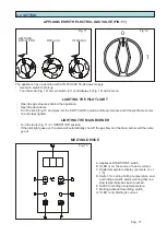
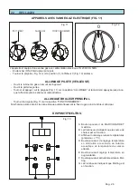
To fit the flue, proceed as follows (Fig. 4)
- remove the flue extension with the basket
supports;
- fit the flue onto the appliance as illustrated;
- tighten the flue to the appliance using the 3
screws supplied with the flue.
Fig. 4
Fig. 5
1.4 CONNECTING UP GAS
INSTALLATION INSTRUCTIONS
Only qualified persons must be entrusted with installation operations, adapting the appliance to different types of
gas, commissioning and eliminating system faults. All current rules and regulations must be complied with.
The gas fittings, wiring and the premises on which the appliance is installed must comply with current rules and
regulations. In particular, for combustion, burners require 2m
3
/h per kW of installed power.
Accident prevention and fire and anti-panic safety regulations must be enforced in places that are open to the
public.
CHECKS BEFORE INSTALLATION
Check on the rating plate inside the door or on the left-hand side that the appliance has been tested and approved
for the type of gas that the user uses.
Check that the nozzles on the appliance are suitable for the available gas supply.
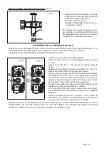
Check on the rating plate that the pressure reducer is adequate to the appliance’s gas supply (Fig. 5).
Unless the customer requests otherwise when placing his order, the appliance has been calibrated by the ma-
nufacturer to use G20 at 20mbar.
If gas supply pressure deviates by more than 10% from nominal pressure, fit a pressure regulator upstream of
the appliance to ensure that nominal pressure is maintained.
Do not reduce the diameter of the pipe between the reducer and the appliance.
Fit a gas filter upstream of the pressure regulator in order to optimise operating efficiency.