background image

35

6.2

Maintenance

1. Keep the test documents up-to-date and make them available.
2. In the menu item 

sa

 of the second Service menu, bring up the number of openings 

co

, the operating hours 

ho

 and the number of diagnoses 

fO

 and record these in 

the maintenance log.

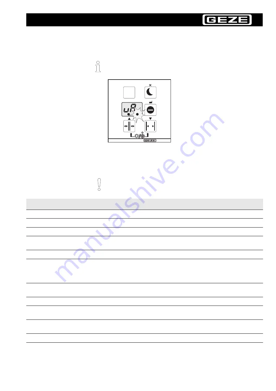
The prescribed maintenance work on the Slimdrive SL and Slimdrive SL-FR 2M are 
to be carried out by properly trained personnel at least once a year or when the 
service display on the display program switch lights up (see figure below).

After completing the maintenance work always carry out the Learn function 
for the door (see Chapter 5.3).

Test object

Action

Remarks

Runner

Check for cleanliness

Clean the runner, if necessary

Roller carriage

Check the wear of the rollers

Remove the wear, if necessary

Floor guide area

Check for smooth operation

Clean the floor routing section, if necessary

Floor routing section 
(brushes)

Check for soiling and hardness

Clean or replace, if necessary

Door leaf

Check for smooth movement

See Chapter 7.1

Toothed belt

Check for wear and damage
Checking tension

Check at the locking device for damage

Replace toothed belt, if necessary
Tighten the toothed belt, if necessary (see 
Chapter 3.7)
Replace toothed belt, if necessary

Locking device

Check the operation

Re-position the locking device, if necessary 
(see Chapter 4.2)

Battery

Check battery voltage

Replace battery, if necessary

Bolts

Check for firm seating

Tighten the bolts, if necessary (for torques refer 
to block diagram)

Modules and
peripherals

Check for correct operation

Replace module, if necessary
(see Chapter 7.1).

Cable

Check for damage and proper mounting

Fasten/replace cables, if necessary

Summary of Contents for Slimdrive SL

Page 1: ...l Slimdrive SL Slimdrive SL FR 2M GB Id No 108722 DE Mat Nr 105128 NL Artikelnr 108727 FR N de suite 108723 SE Mat nr 108726 IT N mat 108724 PL Nr id 108728 ES N m de mat 108725 RU 108729 CZ Mat is 11...

Page 2: ...and hood earth 15 3 17 Connecting alarm contact at locking device optional 16 3 18 Installing cable holders and hood mounting brackets 16 3 19 Connecting transformer and controller 17 3 20 Connecting...

Page 3: ...ation to be carried out Means important note Means additional information Indicates parts of the text that must be read and observed Failure to observe this information may result in injuries and dama...

Page 4: ...ccessible 10 A overload cut out as the line side disconnecting device Protect the display program switch from unauthorised access The detection field of the motion detector in the exiting direction mu...

Page 5: ...er of injury by sharp edges in the drive Danger of injury during installation by freely moving parts Inspection of installed system Measures for security and prevention of pinching impact shearing or...

Page 6: ...0 Block diagram Slimdrive SL drive 70494 0 010 Block diagram Slimdrive SL FR 2M drive 70484 2 0572 Hood Fault elimination Faults and corrective measures DCU1 DCU1 2M controller The diagrams are subjec...

Page 7: ...the block diagram for the number and sequence of sliding blocks 3 Measure out position of the components based on the block diagram 3 3 Installing deflection pulley Place the deflection pulley 1 on tw...

Page 8: ...g blocks at a distance U2 see block diagram from the centre marking and install it with an M6 x 20 Verbus Ripp locking bolt 2 Clamp a foam block 2 under the motor for safety during transport Do not ho...

Page 9: ...locking bolts 2 Test the locking function Lock and unlock bolt 1 The bolt must move smoothly Bolt lock See installation instructions Id No 106944 Use only toothed belt lock with 24 V label 1 Remove th...

Page 10: ...o length 3 Guide toothed belt around crown gear of the motor and deflector 4 Insert the toothed belt between the locking device guide 2 and locking device 3 5 Attach ends of toothed belt to the toothe...

Page 11: ...2 again 3 8 Installing controller 1 Install both tensioning plates 1 to the flat sliding blocks 2 in the runner with M6 x 8 Inbus Ripp locking bolts 2 Place controller 3 on the runner and push tension...

Page 12: ...roller carriage 1 from the side into the runner in the proper position 3 11 Installing optional special roller carriage The special roller carriage prevents tipping with narrow door leaves See block d...

Page 13: ...nd piece and the other threaded rod is in the runner 2 Tighten threaded rods 3 14 Installing side panels 1 Insert a sliding block 2 for the side panel 1 and clamp with M6 x 12 threaded rod 2 Secure th...

Page 14: ...ing bolts into two flat sliding blocks 2 Place transformer on runner and position it tighten the two locking bolts 3 Insert earth cable 1 of the transformer at the earth connector 2 1 2 Do not yet tig...

Page 15: ...Insert the mounting elements 1 for cords rubber cable at the left and right in the groove approx 2 cm from the edge of the hood 4 Screw on with two pan head tapping screws DIN 7981 2 each 5 Attach co...

Page 16: ...od mounting brackets 1 Install hood mounting brackets 2 and fasten to a sliding block with an M6 x 16 Inbus Ripp locking bolt Distribute hood mounting brackets evenly on the runner based on the prevai...

Page 17: ...nnect to cable terminals 3 of the controller 3 20 Connecting geared motor and controller Slimdrive SL Slimdrive SL FR 2M Slimdrive SL 1 Lay rotary transducer cable 1 and motor connection cable 2 to co...

Page 18: ...ough Attach the battery extension cable Id No 10531 to the battery cable if necessary 1 Do not yet attach battery cable to controller The battery is not attached to the controller until commissioning...

Page 19: ...r toothed belt lock shorten if necessary strip and attach insulated wire end ferrules 3 Connect cable to toothed belt lock 3 see terminal connection diagram 4 Place cover 4 on controller and lock in p...

Page 20: ...should be set as narrow as possible without touching the tooth 4 Conduct an operating test in the workshop as described in Chapter 3 25 5 Apply adhesive label Information plate enter date of manufactu...

Page 21: ...t yet been initialised with the Learn function A display program switch is connected The toothed belt lock optional must be locked bolt comb fully engages in toothed belt The bolt lock optional must b...

Page 22: ...If a fault occurs during the operating test the test is aborted and the fault displayed The operating test can be conducted as often as desired The display of the individual test steps on the display...

Page 23: ...g profile with lower edge of bolt lock 5 Screw on the mounting profile Watch the shim 3 for post bolt lock design here see installation diagram 6 Install light barrier profiles sealing strips in accor...

Page 24: ...trips with mounting profile so that the runner is torsion free Push all 7 clamping strips between mounting profile and runner Post bolt lock design position 5 inner terminal strips at height of inner...

Page 25: ...buffers if necessary 2 Move toothed belt until toothed belt lock and driver are positioned in line 3 Connect driver to toothed belt lock Begin with short driver Bolt rear toothed belt lock 1 to short...

Page 26: ...guide 3 so that the toothed belt neither contacts nor has too much air To this purpose loosen 2x Inbus Ripp screws 2 move the locking device guide 3 and tighten the screws 2 again 6 Lightly lubricate...

Page 27: ...any moving parts within the drive unit Starting Learn function 1 Push the display program switch into the controller 2 Clear out detection field of all sensors Use display program switch DCU Id No 10...

Page 28: ...d and the door is ready for operation Checking operation 1 Switch system off 2 Switch system on again 3 Set display program switch to Automatic Diagnosis runs automatically 4 Check function of modules...

Page 29: ...ng widths depending on the type When adjusting the motion detector ensure that the complete opening area is detected see drawing Adjust the sensitivity of the sensor and the detection field accordingl...

Page 30: ...out in the reverse order of installation Danger of injury from swivelling hood When handling the hood always work together with a second person The lock must not scrape the hood The cables must not b...

Page 31: ...e door leaves open and close after each change In the Service mode the door maintains the current operating state and opens and closes accordingly Exception le and fO functions The keys of the display...

Page 32: ...ose door leaves before learning When using a bolt lock set the parameter T to 4 before starting the Learn process Display Description Possible settings l0 Start l1 Checking of rotary transducer l3 Ope...

Page 33: ...ntroller as with a single system At this time the outer door secondary controller is de energised 2 Switch off the inner door 3 Commission the outer door as with a single system During this time the i...

Page 34: ...ood may only be set in place and removed by two people working together Carefully lower the hood via the hood stay cables when removing it When setting the hood in place always lock the hood and press...

Page 35: ...the rollers Remove the wear if necessary Floor guide area Check for smooth operation Clean the floor routing section if necessary Floor routing section brushes Check for soiling and hardness Clean or...

Page 36: ...ger of electric shock Disconnect the system from the 230 V mains network before working on the electrical system Danger of injury due to impact and crushing Secure the door leaves against accidental m...

Page 37: ...er 7 2 Electrical faults Current active fault messages are briefly displayed cyclically 10 sec at the display program switch during operation In addition they are also entered in the e and Oe fault me...

Page 38: ...the tip of the screwdriver The snap catch is released 3 Remove cover 4 Pull off fuse retainer 2 toward the front and replace defective fuse 5 Reattach fuse retainer 6 Set PCB cover in place and snap...

Page 39: ...S2 does not switch or actuation takes longer than 4 minutes 25 Obstruction while opening 2 27 Safety sensor open 1 SIO1 or safety sensor open 2 SIO2 is active 1 28 Motor relay of main PCB defective 29...

Page 40: ...ult in internal computer monitoring 2 70 Fault on DCU101 additional PCB 2 71 Short circuit on DCU101 additional PCB Excessive current through motor 2 2 72 DCU101 motor Motor 2 defective 2 75 DCU101 co...

Page 41: ...ht adjustment 25 mechanical faults 36 test 35 36 Door suspensions hook in 25 Driver 20 25 E End piece installation 13 F Fault electrical 37 mechanical 36 Fault messages 39 Final work 20 G Geared motor...

Page 42: ...or close SIS test 28 Safety sensor open SIO test 28 Service mechanical 34 Service mode functions 32 operation 31 switching on off 31 Side panels installation 13 Special roller carriage optional instal...

Page 43: ...ndenden Richtlinien und Normen The above drives are under the sole responsibility of the above manufacturer developed designed and manufactured in accord ance with the following directives and standar...

Page 44: ...Id No 108722 Modification level 03 Drawing No 70484 9 9848 Printed in Germany Subject to change without notice Middle East U A E GEZE Middle East P O Box 17903 Jebel Ali Free Zone Dubai Tel 971 0 4 88...

Reviews: