


146
[I/O Device]
The settings define which I/O condition to notify the VSM. To configure
these settings, first disable the
Monitoring all type events
option in Figure
3-4.
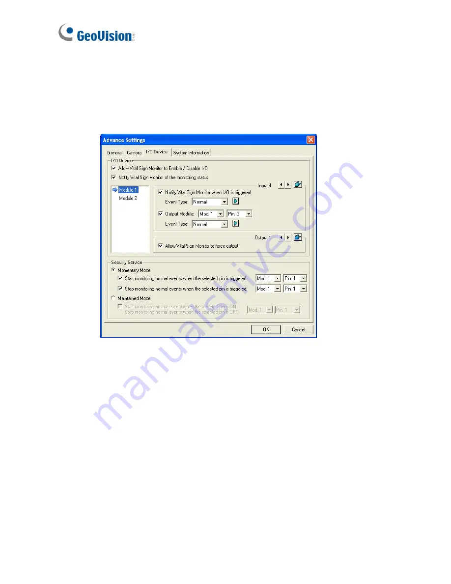
Figure 3-7
[I/O Device]
Notifies the VSM when I/O devices are triggered. Use the
Arrow
buttons to configure each I/O device, or click the
Finger
button to
apply to all I/O devices.
Allow Vital Sign Monitor to Enable / Disable I/O:
Allows the VSM
manually arm/disarm any I/O devices at the subscriber’s site without
interrupting the monitoring.
For example, when an alarm is triggered at the subscriber site, the
VSM operator can turn it off remotely before arriving at the site.
Meanwhile, GV-System still remains on monitoring.
Summary of Contents for GV-CMS Series
Page 1: ...CSV8530 A User s Manual V8 5 3 User s Manual V8 5 3 GV CMS Series ...
Page 10: ...viii ...
Page 253: ...242 Figure 4 53 ...


