


21
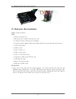
ELECTRONICS BOX INSTALLATION
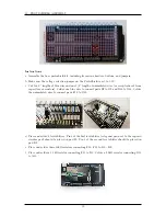
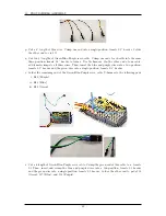
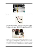
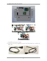
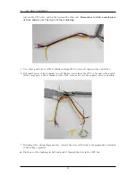
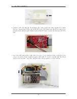
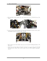
l. Secure the USB wire to the wall of the electronics box using a zip tip saddle and two zip ties as
shown in the images below. Note the position of the zip-tie saddle in between the castle serial
link and the receiver.
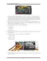
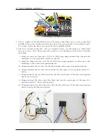
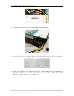
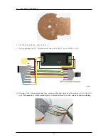
m. Route the brake servo extension cable to the electronics box. Connect the green female 0.1
header wire from the non-Y, Green-Blue-Purple cable of the proto-shield to the yellow male 0.1
header wire of the brake servo extension cable.
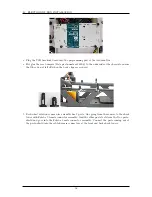
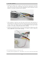
n. Hot glue the connection between these two header wires to the side of the electronics box towards
the front of the chassis.
52
Summary of Contents for AutoRally
Page 1: ...AutoRally Chassis Instructions Version 1 4 June 2018 Georgia Institute of Technology...
Page 2: ......
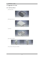
Page 79: ...27 APPENDIX A PARTS Futaba FUTM1725 Charger for Futaba 4PV Glitch Capacitor GPS antenna 75...
Page 80: ...27 APPENDIX A PARTS GPS antenna cable GPS box fan Hallogic OH090U Hall Effect sensors 76...
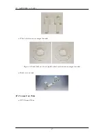
Page 88: ...27 APPENDIX A PARTS 1 M3 4mm screw 27 7 3 GPS Box 8 M3 8mm screws 4 M3 hex nuts 84...
Page 89: ...27 APPENDIX A PARTS 2 M1 4 fan screws 2 M1 4 fan nuts 2 M3 25mm screws 85...
Page 92: ......