

21
ELECTRONICS BOX INSTALLATION
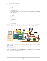
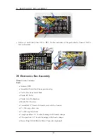
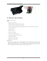
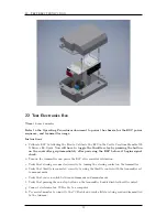
21 Electronics Box Installation
Time
1 hours 30 minutes
Parts
•
Printed electronics box
•
Electronics box assembly from previous step
•
4 completed wheel rotation sensor assemblies
•
2 reserved plastic supports (Baja part number 85420-6) reserved from fuel tank removal
•
3 M3 nylon washers
•
4 M3 hex nuts
•
1 M3
×
6 mm screw
•
3 M3
×
30 mm screws
•
3 M3
×
13 mm nylon spacers
•
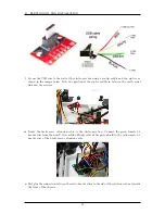
2.0m male weather-proof USB 2.0 cable
•
USB breakout board
•
Zip ties and zip tie saddle
•
Double-sided sticky foam
Instructions
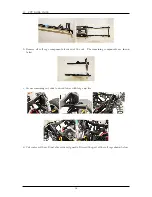
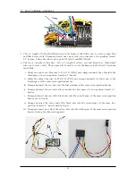
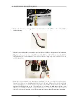
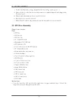
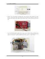
a. Epoxy nuts to the electronics box plastic supports. To do this, first place the nuts into the
supports along with hot glue. Screw the 3 M330 mm screws into the 3 nuts and ensure that
they stand vertically in order to ensure that the nuts are placed horizontally inside the supports.
Refer to the picture below. Remove the screws once the epoxy is set.
48
Summary of Contents for AutoRally
Page 1: ...AutoRally Chassis Instructions Version 1 4 June 2018 Georgia Institute of Technology...
Page 2: ......
Page 79: ...27 APPENDIX A PARTS Futaba FUTM1725 Charger for Futaba 4PV Glitch Capacitor GPS antenna 75...
Page 80: ...27 APPENDIX A PARTS GPS antenna cable GPS box fan Hallogic OH090U Hall Effect sensors 76...
Page 88: ...27 APPENDIX A PARTS 1 M3 4mm screw 27 7 3 GPS Box 8 M3 8mm screws 4 M3 hex nuts 84...
Page 89: ...27 APPENDIX A PARTS 2 M1 4 fan screws 2 M1 4 fan nuts 2 M3 25mm screws 85...
Page 92: ......