

19
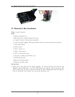
PROTOSHIELD ASSEMBLY
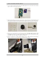
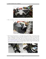
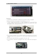
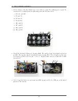
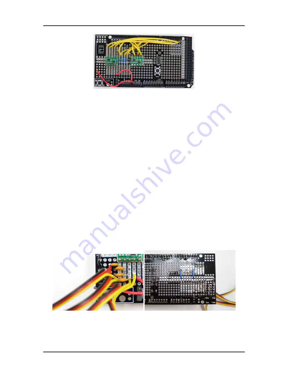
j. Cut four lengths of Yellow-Red-Black servo cable. Two of length 13” and two of length 22”.
These will be used for the wheel rotation sensors. Also, cut one 1/2” length of black wire.
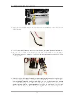
Solder the black wires of all of the servo cables to pads K1 through N1. The order is not
important. Solder the short black wire to connect J1 to H1. On the bottom side of the shield,
connect this row of black wires with a length of uninsulated wire.
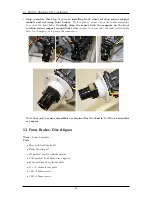
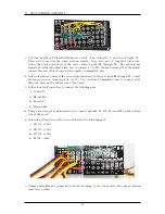
k. Solder all of the red wires of the servo cables introduced in step 8 to pads K3 through N3. Solder
the longer red wire from step 4 to via J3. Use a section of uninsulated wire to connect all of
these red wires on the bottom side of the board.
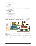
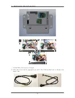
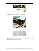
l. Solder four 20pF capacitors to connect the following pads.
i. J4 and J5
ii. K4 and K6
iii. L4 and L7
iv. M4 and M8
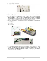
m. Using a short length of uninsulated wire, connect pads H4, J4, K4, L4, and M4 on the bottom
side of the board.
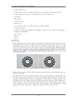
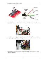
n. Solder the yellow wires of the servo cables into the following pads.
i. M5 (13” cable)
ii. M6 (13” cable)
iii. M7 (22” cable)
iv. L8 (22” cable)
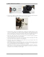
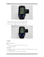
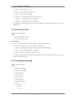
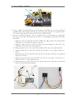
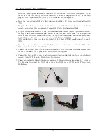
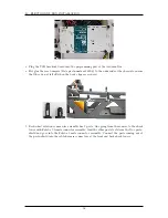
o. Crimp a male Futaba J connector, with outer housing, to the end of each of the wheel rotation
sensor servo cables.
41
Summary of Contents for AutoRally
Page 1: ...AutoRally Chassis Instructions Version 1 4 June 2018 Georgia Institute of Technology...
Page 2: ......
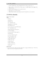
Page 79: ...27 APPENDIX A PARTS Futaba FUTM1725 Charger for Futaba 4PV Glitch Capacitor GPS antenna 75...
Page 80: ...27 APPENDIX A PARTS GPS antenna cable GPS box fan Hallogic OH090U Hall Effect sensors 76...
Page 88: ...27 APPENDIX A PARTS 1 M3 4mm screw 27 7 3 GPS Box 8 M3 8mm screws 4 M3 hex nuts 84...
Page 89: ...27 APPENDIX A PARTS 2 M1 4 fan screws 2 M1 4 fan nuts 2 M3 25mm screws 85...
Page 92: ......


