

19
PROTOSHIELD ASSEMBLY
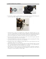
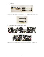
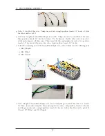
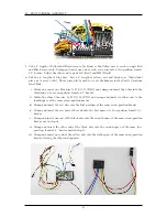
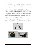
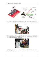
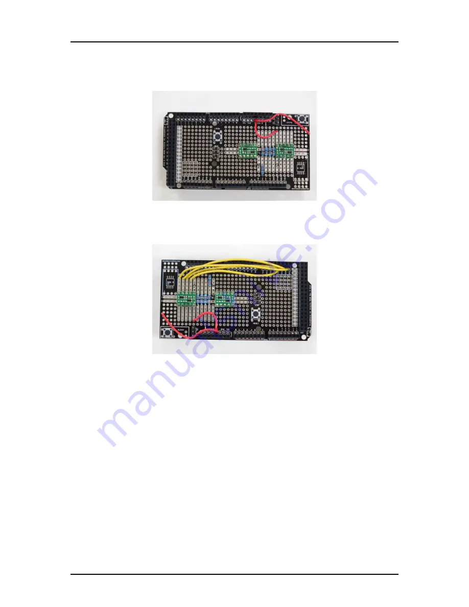
g. Cut two short lengths, one about 1 1/2” and one about 2” of red wire. Solder one end of each
wire to the 5V output pin of the arduino footprint. Solder the other end of the 1 1/2” length
wire to via M9.
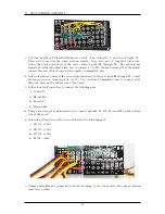
h. Cut four 3 1/2” lengths of yellow wire. Solder these wires to connect pads B5 to D I/O 21 (SCL),
B6 to D I/O 20 (SDA), B7 to D I/O 19 (RX1), and B8 to D I/O 18 (TX1).
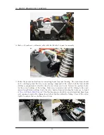
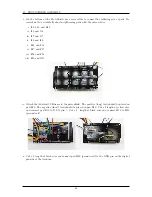
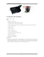
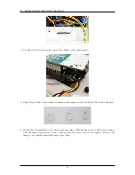
i. Cut seven 1 1/2” lengths of yellow wire. Solder these wires to connect the following via pairs.
i. E10 - D I/O 3
ii. E11 - D I/O 11
iii. E12 - D I/O 5
iv. E13 - D I/O 6
v. E16 - D I/O 8
vi. E17 - D I/O 9
vii. E18 - D I/O 10
40
Summary of Contents for AutoRally
Page 1: ...AutoRally Chassis Instructions Version 1 4 June 2018 Georgia Institute of Technology...
Page 2: ......
Page 79: ...27 APPENDIX A PARTS Futaba FUTM1725 Charger for Futaba 4PV Glitch Capacitor GPS antenna 75...
Page 80: ...27 APPENDIX A PARTS GPS antenna cable GPS box fan Hallogic OH090U Hall Effect sensors 76...
Page 88: ...27 APPENDIX A PARTS 1 M3 4mm screw 27 7 3 GPS Box 8 M3 8mm screws 4 M3 hex nuts 84...
Page 89: ...27 APPENDIX A PARTS 2 M1 4 fan screws 2 M1 4 fan nuts 2 M3 25mm screws 85...
Page 92: ......


