

19
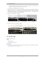
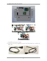
PROTOSHIELD ASSEMBLY
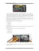
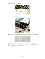
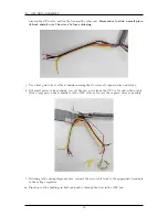
v. On the bottom of the ProtoShield, use excess solder to connect the following sets of pads. Be
careful not to accidentally short neighbooring pads with the extra solder.
i. I19, J19, and K19
ii. I18 and J18
iii. I17 and J17
iv. I16 and I16
v. E18 and F18
vi. E17 and F17
vii. F16 and F16
viii. F19 and G19
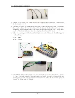
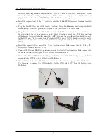
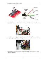
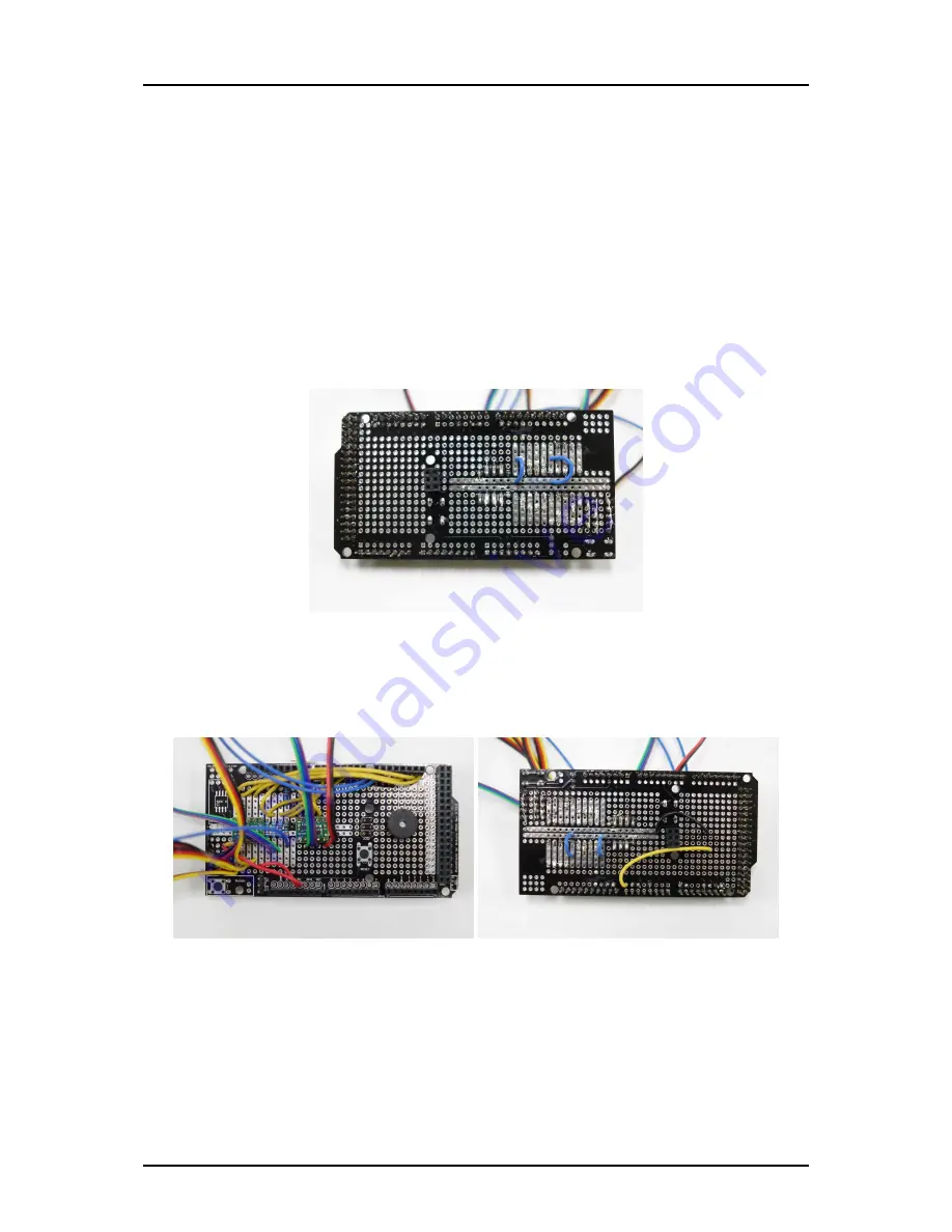
w. Attach the Adafruit 5V Buzzer to the protoshield. The positive (long) lead should be placed in
pad E30. The negative (short) lead should be placed in pad H30. Cut a 2 length of yellow wire
and connect pad E30 to D I/O pin 7. Cut a 1 length of black wire and connect H30 to H23
(ground rail).
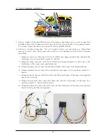
x. Cut a 1 length of black wire and connect pad H22 (ground rail) to the GND pin on the digital
pin side of the Arduino.
44
Summary of Contents for AutoRally
Page 1: ...AutoRally Chassis Instructions Version 1 4 June 2018 Georgia Institute of Technology...
Page 2: ......
Page 79: ...27 APPENDIX A PARTS Futaba FUTM1725 Charger for Futaba 4PV Glitch Capacitor GPS antenna 75...
Page 80: ...27 APPENDIX A PARTS GPS antenna cable GPS box fan Hallogic OH090U Hall Effect sensors 76...
Page 88: ...27 APPENDIX A PARTS 1 M3 4mm screw 27 7 3 GPS Box 8 M3 8mm screws 4 M3 hex nuts 84...
Page 89: ...27 APPENDIX A PARTS 2 M1 4 fan screws 2 M1 4 fan nuts 2 M3 25mm screws 85...
Page 92: ......