


19
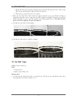
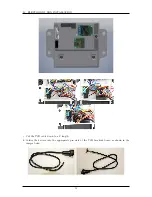
PROTOSHIELD ASSEMBLY
–
26” yellow
–
5” black
•
Servo cable
–
76” yellow-red-black
–
18” green-blue-purple (any 3-conductor ribbon cable, preferably different colors than the
YRB servo cable)
•
4 Male Futaba J-Connectors
–
12 crimps
–
4 housings
•
Female 0.1” Crimped Headers
–
3 single-position
–
3 two-position
–
3 three-position
–
1 seven-position
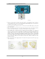
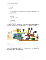
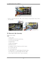
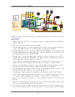
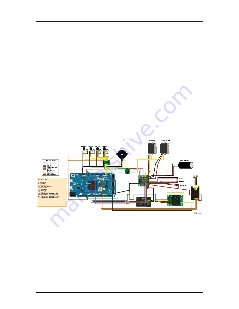
The following diagram shows the schematic for the components within and connected to the Elec-
tronics Box. This schematic defines the connections we will be making on the ProtoShield.
NOTE: A scalable version of the drawings (AutoRally Electronics Box) is available in the folder
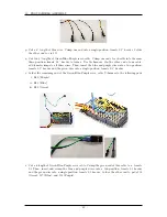
If you have not soldered before, or would like a refresher course, please consider watching this
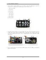
During the following instructions, individual pads on the ProtoShield grid will be identified using
the coordinates defined in the following diagram.
38
Summary of Contents for AutoRally
Page 1: ...AutoRally Chassis Instructions Version 1 4 June 2018 Georgia Institute of Technology...
Page 2: ......
Page 79: ...27 APPENDIX A PARTS Futaba FUTM1725 Charger for Futaba 4PV Glitch Capacitor GPS antenna 75...
Page 80: ...27 APPENDIX A PARTS GPS antenna cable GPS box fan Hallogic OH090U Hall Effect sensors 76...
Page 88: ...27 APPENDIX A PARTS 1 M3 4mm screw 27 7 3 GPS Box 8 M3 8mm screws 4 M3 hex nuts 84...
Page 89: ...27 APPENDIX A PARTS 2 M1 4 fan screws 2 M1 4 fan nuts 2 M3 25mm screws 85...
Page 92: ......


