6
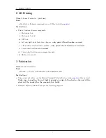
ELECTRIC CONVERSION
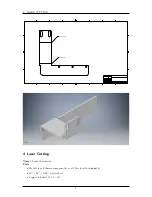
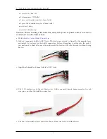
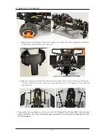
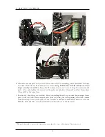
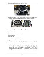
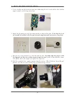
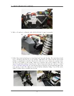
p. This step only applies if you are using the RB kit. In video #6, the ESC is installed. The diff
plate (item #8) in the RB kit has two screw holes that are not aligned with the slots on the
ESC. In that case, create a 3mm wide slot on each side of the ESC, each centered 24.5 mm from
the capacitor side of the ESC, as shown below.
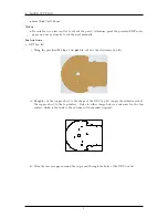
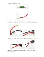
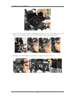
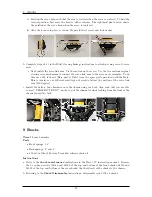
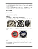
Cover the bottom of the ESC with heavy duty tape, and cut slots into the tape for each center
slot on the ESC, as shown below. Mount the ESC to the diff plate using two M3
×
10mm screws.
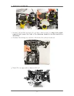
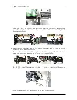
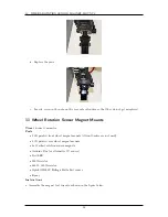
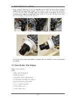
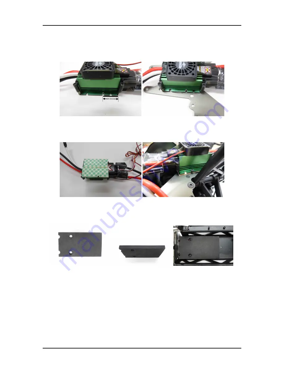
q. Install the battery foam. If you are using the CCB kit, use the included foam. If you are using
the RB kit, use the battery foam you cut.
r.
Do not follow steps in video #8
. However, it is still useful to watch.
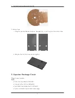
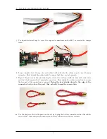
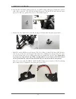
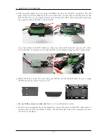
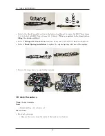
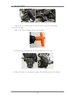
s. In video #9, only perform the steps required to connect the motor and the ESC. Remember to
connect white to white and black to black. Do not follow the steps in the remainder of video
#9. Refer to the photo.
17
Summary of Contents for AutoRally
Page 1: ...AutoRally Chassis Instructions Version 1 4 June 2018 Georgia Institute of Technology...
Page 2: ......
Page 79: ...27 APPENDIX A PARTS Futaba FUTM1725 Charger for Futaba 4PV Glitch Capacitor GPS antenna 75...
Page 80: ...27 APPENDIX A PARTS GPS antenna cable GPS box fan Hallogic OH090U Hall Effect sensors 76...
Page 88: ...27 APPENDIX A PARTS 1 M3 4mm screw 27 7 3 GPS Box 8 M3 8mm screws 4 M3 hex nuts 84...
Page 89: ...27 APPENDIX A PARTS 2 M1 4 fan screws 2 M1 4 fan nuts 2 M3 25mm screws 85...
Page 92: ......


