background image

8

ENGLISH

2.2. PRELIMINARY CHECKS

To ensure a correctly operating automated system, the structure 

of the existing gate or gate to be built must satisfy the following 

requirements:

The  construction  elements  of  the  gate  must  comply  with  the 

provisions of the EN12604 and EN 12605 standards.

Leaf dimensions must not exceed the values indicated in  pa-

ragraph 1.1.

The travel limit mechanical stops, for both opening and closing, 

must be installed.

The structure of the leaves must be sufficiently rigid and sturdy, 

suitable for the automated system.

Leaf movement must be smooth and free of any jamming during 

the entire travel.

Adequately sturdy hinges, in good condition

Check the possibility of fastening the operator, respecting the 

installation dimensions – see paragraph 2.3.

Check if an efficient earth plate is present for electrical connec-

tion to the operator.

Do not use the operator to move safety exits or gates installed 

on emergency routes (see escape routes).


If a pedestrians door is built into the leaf due to be motorised, 

you must add a safety switch on the door, connected to 

the stop input, in order to prevent the automated system 

working while the door is open.


The condition of the gate structure directly influences the safety 

and reliability of the automated system.


We advise you to carry out  the metalwork jobs if any, before 

installing the operator.

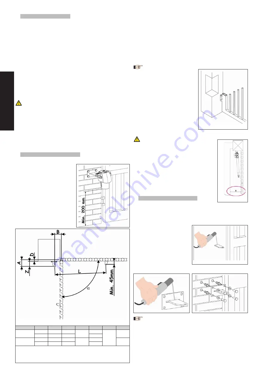
2.3. INSTALLATION DIMENSIONS 

Determine the installation position of the operator by referring to 

figure  4,  where  the  minimum  off-

ground height is specified.

To  determine  the  operator  instal-

lation dimensions, consult figure 5 

and the relevant table.

Fig. 5

Version

a

A

B

a

b

c

L

300

90°

145

145

300

100

45

930

110°

125

125

80

400

90°

195

195

400

150

1110

110°

165

165

120

a

 Useful rod stroke   

b

 maximum dimension  

c

 minimum dimension 

2.3.1. g

eneRal


Rules


foR


deteRmining


the


installation


dimensions

.

To obtain 

90°

 opening of the leaf: 

A+B=C

.

To obtain leaf opening 

greater than 90°: A+B<C

.

Lower  dimensions 

A

  and 

B

  cause  greater  leaf  peripheral 

speed.

Limit the difference between dimension 

A

 and dimension 

within 4 centimetres; higher differences cause considerable 

leaf peripheral speed variations during closing and opening 

movements.

Maintain a 

dimension ensuring that the operator does not 

impact the pilaster, while the leaf is closed.

If the dimensions of the pilaster or the position of the hinge 

do not allow the operator to 

be  installed,  to  respect  the 

determined  dimension 

A

,  a 

niche must be created on the 

pilaster  as  shown  in  figure  6. 

The  dimensions  of  the  niche 

must allow smooth installation 

of  the  motor,  not  limit  motor 

rotation and not obstruct mo-

tor release operations.

When the operator has been installed, check if dimension “X” 

in Fig. 7 is at the minimum of 500 mm. If 

dimension “X” is less than 500 mm, run an 

impact test on the point indicated in Fig.7, 

as described in standard UNI EN 2445, 

and make sure that the measured values 

conform to the specifications of standard 

UNI EN 2453.


If the thrust values are not within the values 

specified in standard UNI EN 2453, the 

zone indicated in figure 7 MUST BE pro-

tected with a protective device confor-

ming to the UNI EN 2978 standard.

2.4. INSTALLING THE OPERATOR 

Fit the rear bracket in the position you have 

just determined. If necessary, the length of the rear bracket 

can be modified in order to respect the installation dimensions 

(Z dimension included).

For iron pilasters, weld the bracket directly on the pilaster (Fig. 

8).

For masonry pilasters, an ap-

propriate  plate  (available 

as a optional item) must be 

used for scew fastening.

Weld  the  rear  bracket  to 

the  plate  and  screw  it 

on, inserting it in the slot  

(Fig. 9).

Secure  all  the  items  on  the 

pilaster using adequate securing systems (Fig. 10).

Fig. 9

Fig. 10

During the operations to secure the rear bracket, use a level 

to check if the bracket is perfectly horizontal.

1.

2.

3.

4.

5.

1.

a–

b–

i–

ii–

Fig. 4

Fig. 4

Fig. 6

Fig. 6

Fig. 7

Fig. 7

Fig. 8

Fig. 8

Summary of Contents for G-BAT

Page 1: ...g bat ENV...

Page 2: ...icated at point 10 The safety devices EN 12978 standard protect any danger areas against mechanical movement Risks such as crushing dragging and shearing Use of at least one indicator light is recomme...

Page 3: ...rasposta nella legislazione nazionale dal DPR n 459 del 24 luglio 1996 Grassobbio 21 Aprile 2009 L Amministratore Delegato D Gianantoni Note per la lettura dell istruzione Leggere completamente questo...

Page 4: ...smissione c Chiave di sblocco d Staffa di fissaggio posteriore e Staffa di fissaggio anteriore f Perni di fissaggio g Anelli elastici 1 1 CARATTERISTICHE TECNICHE Modello G BAT ENV Tensione e frequenz...

Page 5: ...Per ottenere aperture dell anta maggiori di 90 A B C Quote A e B pi basse determinano una velocit periferica dell anta maggiore Limitare la differenza tra la quota A e la quota B entro i 4 centimetri...

Page 6: ...care che l anta possa eseguire tutta l apertura desiderata fermandosi in corrispondenza degli arresti meccanici in apertura Se necessario rimuovere la staffa anteriore e ripetere le operazioni dal pun...

Page 7: ...sull in terruttore differenziale Chiudere la leva di sblocco Fig 20 Esercitare una leggera pressione per far agganciare la leva Muovere manualmente l anta sino al suo arresto Alimentare il sistema Com...

Page 8: ...in Italian National legislation under Presidential Decree No 459 of 24 July 1996 has been declared Grassobbio 21 April 2009 The Managing Director D Gianantoni Notes on reading the instruction Read th...

Page 9: ...perator b Transmission pipe c Release key d Rear fastening bracket e Front fastening bracket f Fastening pins g Elastic rings 1 1 TECHNICAL SPECIFICATIONS Model G BAT ENV Power suply voltage and frequ...

Page 10: ...sions To obtain 90 opening of the leaf A B C To obtain leaf opening greater than 90 A B C Lower dimensions A and B cause greater leaf peripheral speed Limit the difference between dimension A and dime...

Page 11: ...ation see paragraph 6 and make sure that the leaf can perform all the requi red opening stopping at the opening mechanical stops If necessary remove the front racket and repeat operations from point 8...

Page 12: ...using the differen tial switch Close the release lever Fig 20 Exert light pressure to attach the lever Move the leaf by hand until it stops Supply power to the system Command a couple of work cycles...

Page 13: ...r le DPR n 459 du 24 juillet 1996 Grassobbio le 21 Avril 2009 L Administrateur D l gu D Gianantoni Remarques pour la lecture de l instruction Lire ce manuel d installation dans son ensemble avant de c...

Page 14: ...be de transmission c Cl de d verrouillage d Patte de fixation post rieure e Patte de fixation ant rieure f Axes de fixation g Anneaux lastiques 1 1 CARACT RISTIQUES TECHNIQUES Mod le G BAT ENV Tension...

Page 15: ...A B C Pour obtenir des ouvertures du vantail sup rieures 90 A B C Des cotes A et B inf rieures d terminent une vitesse p riph ri que sup rieure du vantail Limiter la diff rence entre la cote A et la...

Page 16: ...nuel voir paragraphe 6 et v rifier que le vantail puisse ex cuter toute l ouverture souhait e en s arr tant au niveau des arr ts m caniques en ouverture Si n cessaire d monter la patte ant rieure et r...

Page 17: ...el Fermer le levier de d verrouillage Fig 20 Exercer une l g re pression pour que le levier s enclenche Actionner le vantail manuellement jusqu son arr t Mettre le syst me sous tension Commander une p...

Page 18: ...odificaciones incorporada a la legislaci n nacional por el DPR n 459 del 24 de julio de 1996 Grassobbio 21 de Abril de 2009 El Administrador Delegado D Gianantoni Notas para la lectura de las instrucc...

Page 19: ...G BAT ENV Istruzioni per l uso Instructions for use Instructions pour l usager Instrucciones para el uso Gebrauchsanleitung Gids voor de gebruiker...

Page 20: ...d installazione Nelle automazioni sono presenti dispositivi di sicurezza fotocellule che impediscono la richiusura del cancello quando un ostacolo si trova nella zona da loro protetta Il sistema gara...

Page 21: ...our of the gate in different function logics consult the installation Technician Automated systems include safety devices photocells that pre vent the gate from closing when there is an obstacle in th...

Page 22: ...Installateur Les automatismes disposent de dispositifs de s curit photocel lules qui emp chent la refermeture du portail en cas d obstacle dans la zone qu ils prot gent Le syst me garantit le blocage...

Page 23: ...nsulte al T cnico instalador Los automatismos est n equipados con dispositivos de seguridad fotoc lulas que impiden el cierre de la cancela cuando un obst culo se encuentra en la zona protegida por di...

Page 24: ...Montage beauftragten Techniker Die Automationen enthalten Sicherheitseinrichtungen Fotozellen die das erneute Schlie en des Tors verhindern wenn sich ein Hin dernis in dem jeweiligen gesch tzten Bere...

Page 25: ...ag van de poort met de verschillende bedrijfslogica s Automatische systemen hebben veiligheidsvoorzieningen fotocel len die verhinderen dat de poort weer sluit wanneer er zich een obstakel in het door...

Page 26: ...sitif de s curit 1 Dispositivo de seguridad 1 Sicherhei tsvorrichtung 1 Veiligheidsvoorziening 1 Dispositivo di sicurezza 2 Safety device 2 Dispositif de s curit 2 Dispositivo de seguridad 2 Sicherhei...

Page 27: ...nte Kunde Klant 4 Tecnico Technician Technicien T cnico Techniker Technicus Cliente Customer Client Cliente Kunde Klant 5 Tecnico Technician Technicien T cnico Techniker Technicus Cliente Customer Cli...

Page 28: ...NOTE NOTES NOTE NOTAS ANMERKUNG OPMERKINGEN...

Page 29: ...NOTE NOTES NOTE NOTAS ANMERKUNG OPMERKINGEN...

Page 30: ...ions qu elle jugera utiles sur ce produit tout en conservant les caract ristiques essentielles sans devoir pour autant mettre jour cette publication Las descripciones y las ilustraciones de este manua...

Page 31: ...e desbloqueo d Brida de fijaci n trasera e Brida de fijaci n delantera f Pernos de fijaci n g Anillos el sticos 1 1 CARACTER STICAS T CNICAS Modelo G BAT ENV Tensi n y frecuencia de alimentaci n 24 Vd...

Page 32: ...a obtener aperturas de la hoja superiores a 90 A B C Cotas A y B m s bajas determinan una velocidad perif rica de la hoja m s elevada Limite la diferencia entre la cota A y la cota B a 4 cent me tros...

Page 33: ...namiento manual v ase p rrafo 6 y compruebe que la hoja realiza toda la apertura deseada y que se detenga cuando alcanza los topes mec nicos en apertura Si fuera necesario retire la brida anterior y r...

Page 34: ...o el interruptor diferencial Cierre la palanca de desbloqueo Fig 20 Ejerza una ligera presi n para que la palanca se engan che Mueva manualmente la hoja hasta que se detenga Alimente el sistema Mande...

Page 35: ...tzgebung durch das Dekret des Pr sidenten der Republik Nr 459 vom 24 Juli 1996 erkl rt ist Grassobbio 21 April 2009 Gesch ftsf hrer D Gianantoni Hinweise zu den Anleitungen Vor der Installation des Pr...

Page 36: ...ragungsrohr c Entriegelungsschl ssel d Befestigungsb gel hinten e Befestigungsb gel vorn f Befestigungsstifte g Elastische Ringe 1 1 TECHNISCHE DATEN Modell G BAT ENV Anschlussspannung und Frequenz 24...

Page 37: ...B C F r ffnungen des Fl gels ber 90 A B C Niedrigere Ma e A und B bewirken eine h here periphere Geschwindigkeit des Fl gels Den Unterschied zwischen Ma A und Ma B auf einen Bereich von 4 cm begrenze...

Page 38: ...r den manuellen Betrieb einrichten siehe Abschnitt 6 und sicherstellen dass der Fl gel die gesamte gew nschte ffnungsbewegung ausf hren kann und an den mechanischen Endanschl gen beim ffnen zum Still...

Page 39: ...ufuhr zur Anlage unterbrochen ist Den Entriegelungshebel schlie en Abb 10 Leicht dr cken damit der Hebel einrastet Den Fl gel mit der Hand bis zum Anschlag bewegen Das System mit Strom versorgen Einig...

Page 40: ...esluit DPR n 459 van 24 juli 1996 is verklaard Grassobbio 21 April 2009 De Algemeen Directeur D Gianantoni Opmerkingen voor het lezen van de instructies Lees deze installatiehandleiding aandachtig doo...

Page 41: ...drijfstang c Ontgrendelingssleutel d Achterste bevestigingsbeugel e Voorste bevestigingsbeugel f Bevestigingspennen g Elastische ringen 1 1 TECHNISCHE EIGENSCHAPPEN Model G BAT ENV Voedingsspanning en...

Page 42: ...hoek van de vleugel van meer dan 90 A B C Als de waarden A en B lager zijn is de omtreksnelheid van de vleugel groter Houd het verschil tussen de waarde A en de waarde B binnen de 4 centimeter als de...

Page 43: ...8 9 10 Fig 16 Zet de aandrijving op handbediening zie paragraaf 6 en con troleer of de vleugel de hele gewenste opening kan uitvoeren en stopt op de plaats van de mechanische aanslagen voor het openen...

Page 44: ...tten Sluit de ontgrendelingshendel Fig 20 Oefen een lichte druk uit om de hendel vast te laten haken Beweeg de vleugel met de hand tot hij niet verder kan Schakel de voeding naar het systeem in Geef e...

Page 45: ...NOTE NOTES NOTE NOTAS ANMERKUNG OPMERKINGEN...

Page 46: ...NOTE NOTES NOTE NOTAS ANMERKUNG OPMERKINGEN...

Page 47: ...ndestens einem Leuchtsignal empfohlen sowie eines Hinweisschildes das ber eine entsprechende Befestigung mit dem Aufbau des Tors verbunden wird Dar ber hinaus sind die unter Punkt 16 erw hnten Vorrich...

Page 48: ...a el derecho dejando inmutadas las caracter sticas esenciales de los aparatos de aportar en cualquier momento y sin comprometerse a poner al d a la presente publicaci n todas las modificaciones que co...

Reviews: