Model FL3102
38
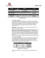
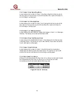
Function
Bit
Position
Conditions
Access
Alarm Latched
5
1 = Latched
0 = Non-Latched
Read/Write
10
8
4
2
Time Delay in Seconds
Alarm Time Delay 2
4
0
0
1
1
Read/Write
Alarm Time Delay 1
3
0
1
0
1
Read/Write
100
75
50
% Sensitivity
Sensitivity
2 2 0 0 1
Read/Write
Sensitivity 1
1 (LSB)
0
1
0
Read/Write
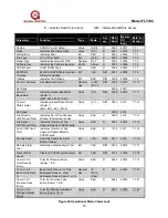
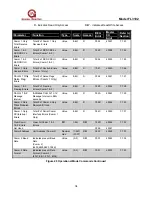
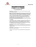
Figure 45 Options
7.7.10 Comm 1 Address
A read returns the address of the FL3102. A write changes the address to the
requested address. The range of the address is 1 to 247 (01 to F7 Hex). After the
address has been changed to the slave unit, the MODBUS communications will
cease because the address has changed; therefore the master will have to
change its query address to the slave’s new address in order to restart the
communications.
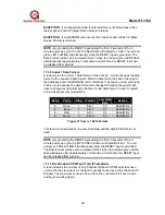
EXCEPTION -
If the EEPROM write error occurs, then the Exception Code 04
(Slave Device Failure) is returned.
NOTE -
By grounding the RESET input during the first 10 seconds of the 2-
minute power-up cycle, the FL3102 Address will default to 1. The red and green
LED’s will flash simultaneously while the RESET input is grounded. The address
will be set to a default of 1 when the red and green LED’s flash alternately after
approximately 10 seconds, at which time the RESET input can be released from
ground.
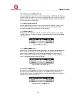
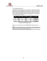
7.7.11 Comm 1 Baud Rate
A read returns the baud rate of the FL3102. A write changes the baud rate to the
requested baud rate. After the baud rate has been changed to the addressed
unit, the MODBUS communications will cease because the baud rate has
changed; therefore the master will have to change its baud rate to the slave’s
new baud rate in order to restart the communications.
Baud Rate
Low Data Byte
Access
19.2K 03
Read/Write
9600
02
Read/Write
4800 01
Read/Write
2400
00
Read/Write
Figure 46 Comm 1 Baud Rate
This function is indicated on the Low Data Byte and the High Data Byte is not
used.

