Model FL3102
41
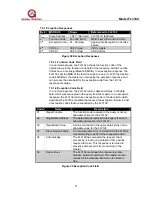
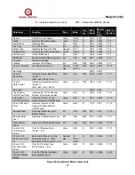
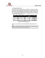
7.7.19 Comm 1 or 2 Total Receive Errors
A read indicates the total MODBUS Comm 1 or 2 Receive Errors that occurred in
the slave device. The maximum count is 255 and then the counter will rollover to
zero and begin counting again. The total errors are an accumulation of the
individual Comm errors listed below:
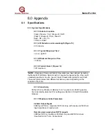
7.7.20 Comm 1 or 2 Bus Activity Rate %
A read indicates the Comm 1 or 2 Bus Activity Rate in percent of this Slave's
addressed node versus other addressed nodes. Range of this value is in hex (0-
64), which translates to decimal (0-100%).
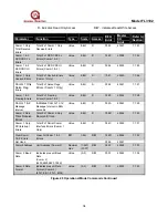
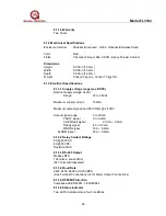
7.7.21 Comm 1 & 2 Function Code Errors
A read indicates the number of Comm 1 & 2 Function Code Errors that occurred
in the slave device. The maximum count is 255 and then the counter will rollover
to zero and begin counting again.
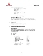
7.7.22 Comm 1 & 2 Starting Address Errors
A read indicates the number of Comm 1 & 2 Starting Address Errors that
occurred in the slave device. The maximum count is 255 and then the counter
will rollover to zero and begin counting again.
7.7.23 Comm 1 Only Total Receive Errors
A read indicates the total MODBUS Comm 1 Only Receive Errors that occurred
in the slave device. The maximum count is 255 and then the counter will rollover
to zero and begin counting again.
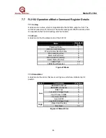
7.7.24 Comm 1 & 2 RXD CRC Lo Errors
A read indicates the number of Comm 1 & 2 RXD CRC Lo Byte Errors that
occurred in the slave device. The maximum count is 255 and then the counter
will rollover to zero and begin counting again.
7.7.25 Comm 1 & 2 RXD CRC Hi Errors
A read indicates the number of Comm 1 & 2 RXD CRC Hi Byte Errors that
occurred in the slave device. The maximum count is 255 and then the counter
will rollover to zero and begin counting again.
7.7.26 Comm 1 Only Overrun Errors
A read indicates the number of Comm 1 Only Overrun Errors that occurred in the
slave device. The maximum count is 255 and then the counter will rollover to
zero and begin counting again.
NOTE -
An overrun error occurs, when the next received byte of data tries to
overwrite an existing received data byte, which has not been processed.
Therefore, the next received byte of data is lost. This can be controlled by
implementing the proper DCS or PLC Error Handling Timing Setting (ex. Reply
Timeout Setting, Delay Time, and Number of Retries) and proper Baud Rate
Setting.

