Model FL3102
5
Table of Figures
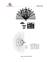
Figure 1 FL3102 Field of View .............................................................................. iii
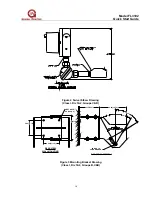
Figure 2 Swivel Elbow Drawing (Class I, Div 1&2, Groups C&D) ......................... iv
Figure 3 Mounting Bracket Drawing (Class I, Div 1&2, Groups B,C&D)............... iv
Figure 4 FL3102 Outline Drawing ..........................................................................v
Figure 5 Wire-Strip Length .................................................................................... vi
Figure 6 Detector Housing and Base .................................................................... vi
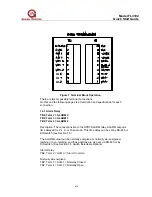
Figure 7 Terminal Block Operation....................................................................... vii
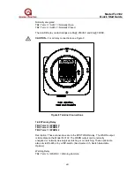
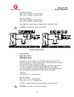
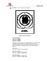
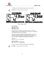
Figure 8 Terminal Connections ........................................................................... viii
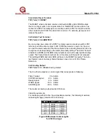
Figure 9 Relay Contacts ........................................................................................ ix
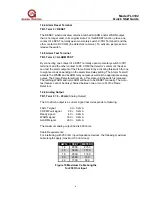
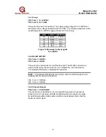
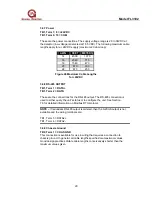
Figure 10 Maximum Cable Lengths for 250 Ohm Input .........................................x
Figure 11 Maximum Cable Lengths for +24VDC .................................................. xi
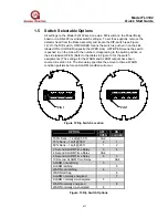
Figure 12 Dip Switch Location.............................................................................. xii
Figure 13 Dip Switch Options ............................................................................... xii
Figure 14 Model FL3102 ....................................................................................... 7
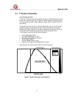
Figure 15 Spectral Response of IR Detectors....................................................... 8
Figure 16 FL3102 Field of View .......................................................................... 12
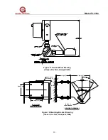
Figure 17 Swivel Elbow Drawing (Class I, Div 1&2, Groups C&D) ..................... 13
Figure 18 Mounting Bracket Drawing (Class I, Div 1&2, Groups B,C&D)........... 13
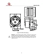
Figure 19 FL3102 Outline Drawing ..................................................................... 14
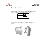
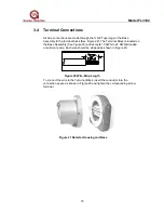
Figure 20 Wire-Strip Length ............................................................................... 15
Figure 21 Detector Housing and Base ................................................................ 15
Figure 22 Terminal Block Operation.................................................................... 16
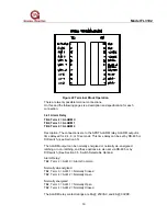
Figure 23 Terminal Connections ......................................................................... 17
Figure 24 Relay Contacts .................................................................................... 18
Figure 25 Maximum Cable Lengths for 250 Ohm Input ..................................... 19
Figure 26 Maximum Cable Lengths for +24VDC ............................................... 20
Figure 27 Dip Switch Location............................................................................. 21
Figure 28 Dip Switch Options .............................................................................. 21
Figure 29 IR Windows ......................................................................................... 22
Figure 30 Troubleshooting Chart......................................................................... 24
Figure 31 FL3102 (DFIR) Final Assembly........................................................... 25
Figure 32 Data Format ........................................................................................ 27
Figure 33 MODBUS Query Messages ................................................................ 28
Figure 34 MODBUS Read Response Messages ................................................ 28
Figure 35 MODBUS Write Query Message......................................................... 29
Figure 36 MODBUS Write Response Message .................................................. 29
Figure 37 Typical Response Times for FL3102 .................................................. 30
Figure 38 Exception Responses ......................................................................... 31
Figure 39 Exception Code Field .......................................................................... 31

