Model FL3102
Quick Start Guide
vii
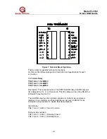
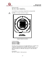
Figure 7 Terminal Block Operation
There are twenty possible terminal connections.
On this and the following pages is a description and specification for each
connection.
1.4.1 Alarm Relay
TB2, Term 2 = ALARM C
TB2, Term 3 = ALARM 1
TB2, Term 4 = ALARM 2
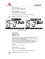
Description: The connections are to the SPDT ALARM relay. ALARM output is
time delayed for 2, 4, 8, or 10 seconds. This time delay can be set by RS-485 or
DIP-switch (see Section 3.5).
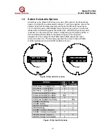
The ALARM output can be normally energized or normally de- energized,
latching or non- latching, and these options are also set via RS-485 or by
DIP-switch. (See Section 3.5 Switch Selectable Options)
Alarm Relay:
TB2, Term 2 = ALM C = Alarm Common
Normally de-energized
TB2, Term 3 = ALM 1 = Normally Closed
TB2, Term 4 = ALM 2 = Normally Open


