Model FL3102
Quick Start Guide
xi
1.4.7 Power
TB1, Term 7, 8 = +24VDC
TB1, Term 9, 10 = COM
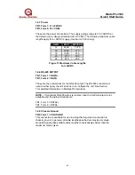
These are the power connections. The supply voltage range is 20 to 36VDC at
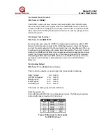
the detector (low voltage is detected at 18.5 VDC). The following maximum cable
lengths apply for a +24VDC supply (maximum 20 ohm loop):
AWG
FEET
METERS
14 4500 1370
16
2340
715
18 1540 470
20
970
300
22 670 205
Figure 11 Maximum Cable Lengths
for +24VDC
1.4.8 RS-485 OUTPUT
TB1, Term 1 = DATA+
TB1, Term 2 = DATA
These are the connections for the RS-485 output. The RS-485 connection is
used to either query the unit’s status or to configure the unit. See Section
7 for detailed information on Modbus RTU protocol.
NOTE –
If redundant RS-485 output is ordered, then the 0-20mA output is not
available and the wiring terminals are:
TB1, Term 5 = DATA2+
TB1, Term 6 = DATA2-
1.4.9 Chassis Ground
TB2, Term 1 = CHAS GND
This connection is available for use in wiring that requires a connection to
chassis ground. In general, all cable lengths specified are maximum values.
Good design practices dictate cable lengths conservatively shorter than the
maximum values given.


