background image

Section 3 Low Power Protection Warning  

If  the  volume  setting  is  too  high,  the  power 
requirement  may  be  greater  than  the  power 
provided   by   computer   or   external   5V   DC 
Charger. At this time, the Low Power Protection 
Warning  will  appear.  Please  reduce  the  volume 
immediately.  Connect  the  two  USB  connectors 
of Micro USB Touch Output and Power Cable to 
the two USB ports on computer. If the volume is 
not  reduced  in  time,  the  Monitor  will  decrease 
the volume and brightness automatically. 

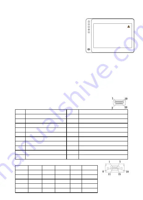
Fig.: Low voltage warning shown 

at upper right corner on screen. 

Chapter 5 Specification 

Section 1 Plug and Play 

The  On-Lap  Monitor  conforms  to  VESA  DDC  standard  and  supports  VESA 
DDC2.  DDC2B is a bi-directional data channel based on I

2

C protocol. The host 

can request EDID information over the DDC2B channel. The On-Lap Monitor is 
able  to  inform  the  host  system  of  its  identity,  and  depending  on  the  level  of 
DDC used, communicate additional information about its display capabilities. 

Section 2 Pin Assignment


1. 

HDMI Connector Pinout 

2. 


2. 

VGA  Connector Pinout              

12 

Fig.: HDMI-A Connector 
(Connect to HDMI port) 

Pin


Name


Pin


Name


1


TMDS Data2+


11


TMDS Clock Shield


2


TMDS Data2 Shield


12


TMDS Clock –


3


TMDS Data2 –


13


CEC


4


TMDS Data1+


14


Reserved


5


TMDS Data1 Shield


15


SCL (I²C Serial Clock for DDC)


6


TMDS Data1 –


16


SDA (I²C Serial Data Line for DDC)


7


TMDS Data0+


17


DDC/CEC Ground


8


TMDS Data0 Shield


18


+5 V Power


9


TMDS Data0 –


19


Hot Plug Detect


10


TMDS Clock+


Pin No.


Name


Pin No.


Name


Pin No.


Name


1


RED


6


RGND


11


NC


2


GREEN


7


GGND


12


SDA


3


BLUE


8


BGND


13


HSYNC


4


NC


9


+5V


14


VSYNC


5


GND


10


SGND


15


SCL


Fig.: VGA connector 
(connect to PC’s 
VGA port) 

Summary of Contents for On-Lap 1002

Page 1: ...Manual of 1002 Read Me Before Usage...

Page 2: ...nd Power Cable 5 Section 3 Connect the 5V 2A Charger Optional 7 Chapter 3 Power On and Off the On Lap Monitor 7 Section 1 Power On and Off the On Lap Monitor 7 Section 2 Monitor Display Setting 7 Sect...

Page 3: ...r 1 Content Description Section 1 On Lap Monitor and Accessories 1 Parts Description 1 Fig On Lap 1002 input output ports Fig 1002 buttons and LED light Description Fig Parts Description of Protective...

Page 4: ...d touch function It is suggested to use the USB port on lap top or manufacturer s 5V 2A Charger 7 Disconnect power source before cleaning Please use soft cloth to clean touch screen monitor When diffi...

Page 5: ...on instructions and precautionary notes Do retain this document for future reference Section 5 Product Maintenance Do not attempt to repair the Product yourself Should any of the following conditions...

Page 6: ...VESA 100 Arm Installation Place the protective cover onto VESA 100 arm as shown in Fig Place the mon itor into the protective cover place the magnetic clip on top short side on the top Fig Protective...

Page 7: ...mark Place On Lap 1002 vertically onto Stand 4 Touch screen will be covered by Stand 4 may affect some Windows 8 touch gestures Stand 4 is not recommended for Windows 8 user who needs to place the mon...

Page 8: ...nector to Micro HDMI port of On Lap 1002 Connect the other end HDMI A type con nector to laptop tablet game console or DVD player s HDMI port Or connect VGA Video Cable s VGA connector to VGA port of...

Page 9: ...f state to On state Press Power Button to activate On Off 2 First time use When Micro USB to USB touch signal and power connect to USB port on computer or 5V DC Charger the power indication light of 1...

Page 10: ...en Setting If the computer is unable to automatically start touchscreen function please use the Tablet PC Setting of the Windows 7 8 1 10 Control Panel to per form touchscreen setting As below Fig ple...

Page 11: ...Please touch the buttons by the fingertip gently Do not press the buttons with stress or continuously which may cause them fail to response Increase up or Decrease down continuously shall be done by t...

Page 12: ...ettings is launched can adjust Color Temp and Color Effect to adjust screen color setting Hue setting can make the image color lean toward green or purple Saturation setting can make saturation more v...

Page 13: ...when input VGA signal can use such function Will automatically adjust VGA setting H Position Moves the display area left and right V Position Moves the display area up and down Clock Adjust the pixel...

Page 14: ...sed on I2 C protocol The host can request EDID information over the DDC2B channel The On Lap Monitor is able to inform the host system of its identity and depending on the level of DDC used communicat...

Page 15: ...0Hz 1366x768 60Hz 1280x1024 60Hz 1280x800 60Hz 1280x768 60Hz 1024x768 60Hz Caution If video output frequency of computer graphic card is out of the above range it may cause the panel damage Support Vi...

Page 16: ...ed to On Lap Monitor s video input port and laptops video output port Image disappears or image size is too big too small or image is not centered The trouble may be caused by VGA video input Please a...

Reviews: