


Assembly
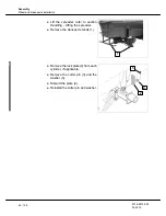
Wheel and brake parts installation
2018-9015-003
03-2015
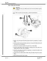
6.5.2
Air brake assembly
Step 1: Brake parts assembly
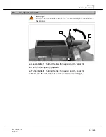
Attention!
Do not exceed 8.27 bar when connecting the air supply to the brake
system.
9
4
5
6
1
2
7
8
3
6
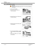
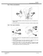
● Build air pressure in the brake system to rotate the ''S'' camshaft (4):
- Connect the air brake outlets of a tractor to the spreader air brake
emergency line (red hose) and service line (yellow/blue hose). Make
sure the pressure is maintained between 4.82 to 6.90 bar. NEVER
EXCEED 8.27 bar.
OR
- Connect a compressor to the emergency line (red hose). Make sure
compressed air is filtered and regulated between 4.82 to 6.90 bar.
Attention!
Never exceed 8.27 bar.
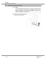
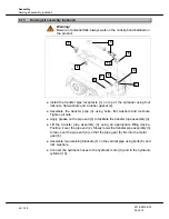
● Install the upper brake lining (1) over the hub receptacle (2). Make sure the
brake lining is well seated on the anchor pins (3) and the ''S'' camshaft (4).
● Hook the blue spring (5) on the return spring pin (6) located inside the frame
lining.
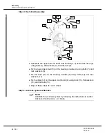
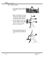
● Position the lower brake lining (7) near the hub assembly in order to hook
the other end of the blue spring (5) on the return spring pin (6).
● Position the lower brake lining (7) under the hub receptacle (2). Make sure
the brake lining is well seated on the anchor pins (3) and the ''S''
camshaft (4).
● Using the brake spring pliers (8), install the two retaining springs (9) between
the upper and the lower brake lining frame. Repeat these steps for each
wheel.