background image

Masoneilan SVI II AP Digital Positioner Quick Start Guide


=

75

© 2015 General Electric Company. All rights reserved

.

ES-699 Rev AA
Page 9 of 16

7

DESCRIPTION OF INTRINSICALLY SAFE MARKINGS (Applies to “Easy 
Smart” version only)

Applicable Model Numbers:
SVI2-abcdefgh, where “a” thru “h” can take on the following values:
a = 1 ; b = 1 ; c = 1 ; d = 1, 2 ; e = 3 ; f = 1 ; g = 1,2 ; h = 3,4

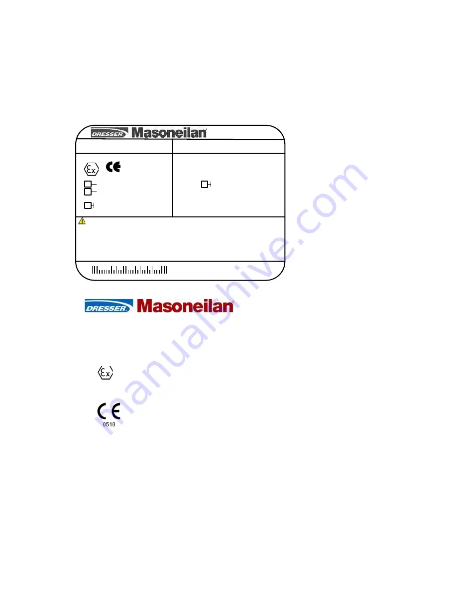
The label may not appear exactly as shown, but must contain the following information 
listed below.  Other information is allowed on the label.

II 3G Ex ic IIC T6

Avon MA USA

WARNING

REFER TO ES-699 FOR ADDITIONAL CAUTIONS OR WARNINGS
Supply Connection Wiring  Rated for 5ºC Above Max Ambient
MODEL: SVI2-1bcdefgh
30 Volts, 4-20mA, 80 PSI
Type 4X-IP66

DO NOT OPEN EVEN WHEN ISOLATED WHEN 
FLAMMABLE / DUST ATMOSPHERES ARE 
PRESENT

ZELM 05ATEX0280X

SN-nnywwnnnn

Operating Temp –40ºC to +85ºC

T6 Ta=60ºC, T5 Ta=75ºC, T4 Ta=85ºC 

055201-188-779

Rev G

PERMANENTLY MARK THE PROTECTION TYPE
CHOSEN. ONCE THE TYPE HAS BEEN MARKED, IT
CAN NOT BE CHANGED.

II 2G Ex ia IIC T6

0518

Ex ia IIC T6

IECEx FMG 07.0007x

IECEx

II 2D Ex ia IIIC T96°C

7.1

Manufacturers Name and Location

Avon MA – 02322 – USA

7.2

Markings: 

(ATEX)

{Explosion Protected Mark}

{CE Conformity Marking, QAN 
Notified Body Number}

ZELM

{Certifying Agency}

Summary of Contents for SVI II AP

Page 1: ...GE Oil Gas Masoneilan SVI II AP Digital Positioner Quick Start Guide Rev N GE Data Classification Public ...

Page 2: ...ING OF THE REQUIREMENTS FOR SAFE OPERATION OF MECHANICAL AND ELECTRICAL EQUIPMENT IN PO TENTIALLY HAZARDOUS ENVIRONMENTS THEREFORE THESE INSTRUCTIONS SHOULD BE INTER PRETED AND APPLIED IN CONJUNCTION WITH THE SAFETY RULES AND REGULATIONS APPLICABLE AT THE SITE AND THE PARTICULAR REQUIREMENTS FOR OPERATION OF OTHER EQUIPMENT AT THE SITE THESE INSTRUCTIONS DO NOT PURPORT TO COVER ALL DETAILS OR VARI...

Page 3: ...e Full Trial Version 20 Mounting the SVI II AP 21 Necessary Precautions 21 Mounting the SVI II AP on Rotary Valves 22 Travel Sensor Alignment 24 Mounting the SVI II AP on Reciprocating Valves 25 Checking the Magnet 29 Installing the SVI II AP for Double Acting Operation 30 Connecting the Tubing and Air Supply 33 Connecting the Air Supply 34 Wiring the SVI II AP 34 Connecting to the Control Loop 35...

Page 4: ...II AP 44 Configuration 46 Configuration with Pushbuttons 46 Viewing Status Messages 48 VIEW DATA Settings 48 Calibration 49 Check out with a HART Handheld Communicator 53 Maintenance 55 SVI II AP Maintenance 55 Repair 55 Tools Needed for Cover Replacement 55 Display Cover Removal and Installation 56 Specifications and References 59 Physical and Operational Specifications 59 Hazardous Location Inst...

Page 5: ...pressure of up to 100 and double acting up to 150 psi Entered edits from Sandro Esposito and Stephane Leledy M 09 2013 Added the Load Limits sections and a cross reference to it from the wiring installation Updated ES 699 to Rev Y N 10 2015 Updated the Load Limits section Updated ES 699 to Rev AA Updated Disclaimer statement Added information on position retransmit switches Removed Remote Position...

Page 6: ...Page Left Blank Intentionally ...

Page 7: ...fines the documentation symbols Safety Symbols Indicates a potentially hazardous situation which if not avoided could result in serious injury or death Indicates a potentially hazardous situation which if not avoided could result in instrument or property damage or data loss Indicates important facts and conditions WARNING CAUTION NOTE 1 Safety Information ...

Page 8: ...of tools or equipment during installation Under normal operation compressed supply gas is vented from the SVI II AP to the surrounding area and may require additional precautions or specialized installations Intrinsically Safe Installation Products certified as explosion proof or flame proof equipment or for use in intrinsically safe in stallations MUST BE Installed put into service used and maint...

Page 9: ...ng and testing to verify the need for engineering or administrative controls to eliminate or reduce hazardous noise levels Installation in poorly ventilated confined areas with any potential of gases other than oxygen being present can lead to a risk of personnel asphyxiation Use only genuine replacement parts which are provided by the manufacturer to guarantee that the products comply with the es...

Page 10: ...This page intentionally left blank ...

Page 11: ...inless steel wetted parts for durability Intrinsically Safe Flameproof and Explosion proof designs are offered as standard The High Flow version is capable of 2 2 Cv air throughput Some of the SVI II AP options include marine grade construction local indicating LCD with push buttons for local calibration position transmitter discrete outputs double acting not available for the High Flow version an...

Page 12: ...Figure 2 SVI II AP Components Figure 3 SVI II AP High Flow Components SVI II AP Cover SVI II AP Assembled Electronics Module Pneumatic Train and Cover I P Module Relay Manifold Pneumatic Relay I P SVI II AP Cover Electronics Module Cover Relay I P Manifold I P Module ...

Page 13: ...p No Procedure Reference 1 Attach mounting bracket to the actu ator See page 21 for rotary valve and reciprocating valve instructions 2 Install the SVI II AP magnetic assem bly rotary valves only See page 21 for instructions 3 Assemble the SVI II AP on the bracket that is mounted to the valve actuator See page 21 for rotary valve and reciprocating valve instructions 4 Install the Remote Position S...

Page 14: ... of the pneumatic block are tapped 1 4 NPT The output port 1 is toward the front while the supply is toward the back Two pressure gauges output on top supply port on bottom are located on the front of the pneu matic block The supply and output connections for the SVI II AP High Flow Figure 5 on page 15 located on bottom and leftside of the pneumatic block are tapped 1 2 NPT Maximum allowable air s...

Page 15: ...ed Figure 5 SVI II AP High Flow Air Ports on Single Acting Positioner Double Acting Positioner Connect Output 1 labeled I to the inlet port of the actuator and Output 2 labeled II to the opposing actuator port see Figure 6 Figure 6 Air Ports on Double Acting Positioner Output Supply Output I Supply Output II ...

Page 16: ...guration and Calibration The SVI II AP also has two modes for handling of faults and power up Reset and Failsafe When commissioning or checking a control valve with SVI II AP fully installed the following steps are recommended Change mode to Manual mode Examine and adjust all CONFIGuration items Enter Calibration mode Run STOPS to automatically calibrate stroke Run autoTUNE to set dynamic response...

Page 17: ...o the next item in the menu or to increment the value currently shown in the digital display When used to increase a displayed value holding this button down causes the value to increase at a faster rate NOTE When an exclamation point appears in the SVI II AP display window it indicates that there is instrument status available Figure 7 SVI II AP Display Pushbuttons Select Forward Back ...

Page 18: ...SVI II AP parameters cannot be inadvertently changed by the buttons Several levels of pushbutton locks are provided Table 2 Pushbutton Lock Security Level Level Access Security Level 3 Allow Local Buttons Buttons on the SVI II AP are fully enabled Security Level 2 Lock Out Local Calibration and Configuration Use the buttons to per form operations in normal operating mode and manual mode Do not go ...

Page 19: ...n and calibration are not permitted by the local interface or by remote communications Pushbuttons ValVue and handheld are locked out except to examine configuration calibration and position This is sim ilar to Security Level 1 shown in the Pushbutton Lock Security Level table Figure 8 Connections to Electronics Module via Terminal Board Display Remote Process Variable Position Retransmit Position...

Page 20: ... Server 2008 Windows 7 64 MB RAM a serial or USB port connected to a HART modem and a CD ROM drive ValVue Full Trial Version The SVI II AP comes with a copy of ValVue Trial Version software that can be used for sixty days without a license After the 60 day trial period ValVue must be registered ValVue full version provides advanced diagnostic maintenance capabilities and basic calibration and conf...

Page 21: ...stalling or replacing a positioner on a control valve ensure that If the valve is located in a hazardous area make sure the area has been certified as safe or that all electrical power to the area has been disconnected before removing any covers or disconnecting any leads Shut off air supply to the actuator and to any valve mounted equipment Ensure the valve is isolated from the process by either ...

Page 22: ...r any position of the valve and actuator 2 Bolt the extension shaft to the valve position take off shaft using a 1 4 28 UNF socket flathead screw Secure the machine screw holding the extension shaft with a torque of 144 in lbs 16 269 N m 3 On internal valve pressure the thrust shaft is pushed out to the mechanical stops usually a thrust bearing On valves where the valve position take off is mounte...

Page 23: ...er so that the magnet axis is vertical when the valve is in the closed position 7 Align the end of the magnet holder flush with the end of the mounting bracket Secure the magnet holder with two M6 set screws 8 Slide the V Seal over the magnet holder 9 Secure the SVI II AP onto the mounting bracket using four M6 x 20 mm socket head cap screws 10 Ensure no interference exists with the position senso...

Page 24: ...Rotary Mounting System Stroke Direction Magnet Orientation Valve Position SensorCounts Rotary 60 Rotation Clockwise or counter clockwise rotation 0 Closed 0 0 1000 60 Rotation Clockwise with increas ing setpoint 45 Full Open or Full Closed 8000 1500 or 8000 1500 60 Rotation Counter Clockwise rota tion with increasing set point 45 Full Open or Full Closed 8000 1500 or 8000 1500 General Rule for oth...

Page 25: ...ng valve consists of mounting the unit on the actuator that is attached to the valve This section describes the procedure for mounting the SVI II AP on Reciprocating Valves using Masoneilan s 87 88 Multi Spring actuators as an exam ple Mounting the SVI II AP on a Reciprocating Actuator Tools required 7 16 Combination Wrench 2 required 3 8 Combination Wrench 1 2 Combination Wrench Phillips Head Scr...

Page 26: ...uires using air pressure in the actuator to fully stroke the actuator For air to retract actuators vent the actuator of air pressure 5 Thread the take off rod to the actuator stem connector Refer to Figure 12 on page 27 Ensure that the travel pointer located on the coupling is correctly positioned 6 Attach the right hand threaded rod end to the SVI II AP lever using a 1 4 20 x 1 cap screw and nut ...

Page 27: ...ghten both turnbuckle lock nuts Refer to Figure 11 12 For reciprocating valves the adjustable link turnbuckle must be parallel to the valve stem To ensure linearity in positioning verify that the hole in the lever aligns with the indicating hole in the bracket when the valve is in the closed position Check that the bracket is mounted using the proper holes Refer Table 4 on page 28 13 Mount the SVI...

Page 28: ... 5 63 5 mm D C 2 90 73 66 mm 23 0 5 0 8 12 7 20 32 mm B A 5 25 133 35 mm 23 0 8 1 5 20 32 41 5 mm C B 5 25 133 35 mm 23 1 5 2 5 41 5 63 5 mm D C 5 25 133 35 mm 2015 General Electric Company All rights reserved 28 GE Oil Gas Dismantling the SVI II AP from Reciprocating Valves WARNING Before carrying out any work on the device power off the instrument or ensure that the local conditions for potentia...

Page 29: ... Checking the Magnet There are two methods of checking the SVI II AP magnet Perform a visual inspection Use ValVue to check the magnet Performing a Visual Inspection To perform a visual inspection refer to Table 3 on page 24 and ensure that the magnet is correct ly oriented for the actuator valve configuration ...

Page 30: ...ng valve po sitioner configurations To mount the kit 1 Set valve to the closed position 2 Install the mounting assembly to the yoke Figure 14 using helical spring washer 5 16 flat washer 5 16 and hex screw 5 16 18x44 5 1 75 LG Figure 14 84 85 86 Actuator NOTE Mount all components snug enough to stay in place but loose enough to tap with rubber hammer into final position Lever Rod end Kit Mount Bra...

Page 31: ...ke Other stroke settings are as in Figure 15 Figure 15 Stroke Settings 4 Mount take off bracket to stem block at angle which keeps turnbuckle assembly parallel to stem Figure 16 using a For top two plain 5 16 flat washers helical spring washer 5 16 two hex nuts 5 16 18 regular b For bottom hex nut regular 1 4 20 and hex screw 1 4 20 UNC x 22 2 88 LG Figure 16 Bracket Configuration Strokes 5 2 50 a...

Page 32: ...ition Figure 17 and connect to take off bracket Figure 17 Magnet Position with Valve Closed 6 Verify lever is in correct position with valve closed Adjust rod ends if necessary Figure 18 Lever Alignment 7 Mount the SVI II with M6 1 screws 8 Cycle the valve open to close verifying proper components movement and that rod ends move free and clear from other components ...

Page 33: ...or Double acting actuator Pipe output pressure port one I for one side of the actuator and output pressure port two II for the other side of the actuator 3 Air supply Supply pressure for single acting SVI II and AP High Flow 20 100 psi 1 4 6 9 bar 138 690 kPa Supply pressure for double acting SVI II AP 25 150 psi 1 73 10 4 bar 172 4 1034 kPa Minimum tubing diameter 1 4 6 mm x 4 mm NOTE The SVI II ...

Page 34: ...spring range of the actuator but may not exceed the rated actuator pressure Refer to the valve or actuator instruction manual Wiring the SVI II AP In order for the SVI II AP to communicate the positioner data the SVI II AP positioner must be physically connected to a HART communication The procedure below outlines wiring the SVI II AP WARNING Comply with current national and local regulations for ...

Page 35: ...oltage at the SVI II AP must be 9 V at the maximum current of 20 mA Signal to the SVI II AP must be a regulated current in the range 3 2 to 22 mA Controller output circuit must be unaffected by the HART tones which are in the frequency range between 1200 and 2200 Hz Frequency range of the HART tones must have a circuit impedance of more than 220 Ohms typically 250 Ohms HART tones may be imposed by...

Page 36: ...mote PC running ValVue software via a modem connected to the PC s se rial or USB port The PC which is not intrinsically safe must be connected to the circuit on the safe area side of the intrinsic safety barrier if the valve is located in a hazardous area The SVI II AP can be operated calibrated configured and interrogated either by using local pushbutton and display or by using a PC running ValVu...

Page 37: ...ower range values must be 4 mA to 14 mA Use the following procedure to ensure that the SVI II AP is properly powered 1 Connect a DC voltmeter across the input terminals For an input current between 4 and 20 mA the voltage varies between 11 V and 9 V respective When voltage exceeds 11 V check that polarity is correct If voltage is less than 9 V and polarity is correct voltage compliance of current ...

Page 38: ...n Figure 20 Intrinsically Safe Installation Hazardous Area Non Hazardous Area Power Supply 220 Ohms HART compliant control system output card HART Modem SVI II AP DPI620 ValVue Power Supply 220 Ohms HART compliant control system output card HART Modem SVI II AP DPI620 ValVue Barrier Resistance Single Channel Zener Barrier ...

Page 39: ...y with pushbuttons Perform all procedures in this section before putting the SVI II AP into operation Check Out Procedures SVI II AP checkout consists of physical and operational checkout procedures The physical check out procedures include Inspecting Actuator Linkages or Rotary Adapter on page 40 Verifying Mounting and Linkage Adjustment on page 40 Checking the Magnet on page 40 Checking the Air ...

Page 40: ...re two methods of checking the SVI II AP magnet Perform a visual inspection Use ValVue to check the magnet Performing a Visual Inspection You must remove the positioner from the bracket to visually inspect the magnet orientation For rotary valves such as a Camflex or for actuators with rotation of less than 60 the magnet assembly must be aligned as shown in Figure 21 For rotary valves with rotatio...

Page 41: ...t up with a HART Modem in a HART compliant communications loop install ValVue on the computer that is connected to the HART modem Run ValVue Select the installed positioner from the list of Connected Devices Select the Check tab to view the current operating conditions of the selected positioner 2 Read Raw Sensor Data When the valve is closed the value should be between 1000 and 1000 for a recipro...

Page 42: ...Teflon tape can shred into particles that are harmful to the pneumatic components Checking the Electronic Module Connections WARNING Do not remove the instrument cover or connect to an electrical circuit in a Hazardous Area unless the power is disconnected All connections to electronic module in the SVI II AP are made through the terminal board The SVI II AP terminal board has a terminal block wit...

Page 43: ...SVI II AP is turned on it is advisable to apply the air supply before applying the electrical input signal Solid State Switch 1 and 2 Optional Optional 4 20 mA Out Position Transmit Optional Optional Table 6 SVI II AP Models and Functionality Continued Available Functionality Positioner Model Number Display Remote Process Variable Position Retransmit Position Input Configuration Lock Jumper 4 20 m...

Page 44: ...ith local display use Val Vue Lite and a PC with a HART modem or a HART Handheld Communicator NOTE When an SVI II AP is turned on it is advisable to apply the air supply before applying the electrical input signal Powering Up the SVI II AP WARNING This process can cause the valve to move Before proceeding be sure the valve is isolated from the process Keep hands clear from moving parts NOTE When a...

Page 45: ...meters installed at the factory The positioner cycles through the NORMAL cycle menu and LCD displays the following values PRES Pressure unit of measurement and value SIGNAL POS Position An exclamation point appears in the top left corner of the display window to indicate that there is further instrument status available 3 Proceed to Configuration and Calibration For firmware version 3 2 1 the supp...

Page 46: ...w SVI II AP configuration data 1 Access the VIEW DATA menu from the MANUAL menu by pressing the button 2 In the VIEW DATA menu press to examine the configuration 3 Press to scroll through and observe the factory configuration 4 Press until MANPOS appears 5 Select with 6 When the adjustment screen appears stroke the valve open by holding down The rate of set point change is slow to begin but increa...

Page 47: ...nfiguration options you must perform Configuration before you perform Calibration when installing the SVI II AP for the first time If a change is made in the Air to Open Air to Close configuration option or if you move the SVI II AP to a different valve or make any change to the valve position linkage you must run the find STOPS calibration again Figure 24 CONFIGure Menu ...

Page 48: ...ositioner was powered without air a Position Error or POSERR can appear 3 Press to view all faults 4 Press to return to MANual menu 5 Press until CLR ERR appears 6 Press CLR ERR WAIT appears for a second or two VIEW DATA Settings Table 7 VIEWDATA Settings Typical Setting Optional Setting SINGLE DOUBLE ATO ATC LINEAR EQUAL 30 EQUAL 50 QUICK 50 CUSTOM CAMFXEQ PSI BAR KPA 0 00 TS OFF 2 00 TS ON 4 00 ...

Page 49: ...II AP 1 Observe the display following power up The SVI II AP powers up in the previously active mode either MANUAL or NORMAL operating mode In NORMAL mode the display alternates between POS and SIGNAL In MANUAL the display alternates between POS M and SIG 2 With MANUAL mode displayed press to select the MANUAL mode 3 Press again CONFIG appears Pressing again brings CALIB 4 Select CALIB by pressing...

Page 50: ...re 25 provides access to all the calibration functions for the SVI II AP If a change is made in the Air To Open Air To Close configuration option or if you move the SVI II AP to a different valve or make any change to the valve position linkage you must run the find STOPS calibration again Figure 25 CALIBration Menu ...

Page 51: ... positioning response WARNING DO NOT perform STOPS while the valve is controlling the process DO NOT perform Auto Tune while the valve is controlling the process To auto tune the SVI II AP 1 Press to begin the autoTUNE procedure As autoTUNE proceeds numerical messages display indicating the procedure is working 2 When autoTUNE is complete TUNE appears 3 Press repeatedly until SETUP appears 4 Press...

Page 52: ...res Normal Cycling Menu Normal Manual View Data View ERR CLR ERR Manual Mode Cycling Menu View Data Menu View Errors Menu Instant Action Normal Manual View Data View ERR CLR ERR Manual Setup MAN POS value value Config Config Calib any key Calib Menu Menu Pressing any key while in Normal cycling moves to Normal Mode ...

Page 53: ...figuration lock jumper is in the unlock position When the jumper is in the lock position shorting the two pin header the handheld is not permitted to make any changes How ever parameters are readable If fault messages appear they must be handled before proceed ing with HART communications Before communications proceeds all error messages must be cleared For example the following message is display...

Page 54: ...ine 6 EXAMINE press 8 Scroll down to 5 read status 9 Read message 10 Press OK 11 Repeat OK to read all messages until the display returns to read status 12 Scroll down to 6 clear status press 13 If clear fault codes not completed appears press OK and read the message Position Error for example or go to the troubleshooting guide 14 Correct the problem Is the air supply on and then go to clear statu...

Page 55: ...a unless the power is disconnected If natural gas is supplied natural gas may escape from the SVI II AP on removal of the cover or components Repair Replacement of the Pneumatic Relay I P and cover with or without display are the only field re pairs permitted Only qualified service personnel are permitted to make repairs Only factory supplied parts are permitted This includes not only the major as...

Page 56: ...with a solid cover and would like to upgrade to a display cover follow the instructions below for removal and installation Removing the SVI II AP Display Cover To remove the SVI II AP display cover 1 Using a 5 mm Hex key unscrew the four screws around the perimeter of the SVI II AP cover 2 Lift the cover off the positioner Figure 28 SVI II AP Pneumatic and Display Covers Pneumatic Cover Cover Disp...

Page 57: ...e SVI II AP housing 3 Connect the cable from the display into the LCD connector on the terminal board 4 Ensure that the gasket is in its groove in the housing 5 Place the cover over the screw mounts 6 Tighten the four screws with the 5 mm hex key 7 After installing the new display power up the unit refer to Powering Up the SVI II AP on page 44 of this guide for further information NOTE The cover o...

Page 58: ...This page intentionally left blank ...

Page 59: ...Effect Less than 0 2 after 2 days at 104 F 40 C 95 Relative Humidity Insulation Resistance Greater than 10 G Ohms at 50 RH MTBF 49 years based on MIL handbook calculation for electronic parts and field data on mechanical parts Electromagnetic Compatibility Electrostatic Electrostatic discharge No effect with contact discharge level of 4KV and air discharge level of 8 kV IEC 1000 4 2 Radio frequenc...

Page 60: ...ime constants dead zone and magni tude characterization parameters Auto Tune is opti mized for 5 step changes with negligible overshoot After the Auto Tune process is completed the user can further adjust the positioner tuning parameters to more conservative or to more responsive values Proportional gain 0 to 5 displayed as 0 to 5000 Integral time 0 to 100 seconds displayed as 0 to 1000 1 10s Deri...

Page 61: ...struction Material Specifications Housing and Cover Aluminum ASTM B85 SG100A standard Stainless Steel optional Weight Standard Flow Model Aluminum 7 4 lbs 3 3 kg Stainless Steel 16 lbs 7 3 kg High Flow Model With Display 9 4 lbs 4 2 kg Without Display 8 9 lbs 4 0 kg Relay and Manifold Standard Flow Model Single Acting PPS 300 Series Stainless Steel nitrile diaphragms Double Acting 300 Series Stain...

Page 62: ...ressure returns after a period without air supply pressure Always set control set point to 0 and put the process control system in manual for smooth recovery from air supply failure Loss of Input Signal Actuator Output fails to atmosphere Output Pressure 0 150 psi 10 3 bar max 2015 General Electric Company All rights reserved 62 GE Oil Gas Table 12 System Connectivity HART Physical Device Type Val...

Page 63: ...y flow coefficient Loading CV 2 2 Venting CV 2 2 Air Consumption 0 28 scf min 8 0 sl min at 30 psi 2 1 bar supply 0 35 scf min 10 5 sl min at 45 psi 3 1bar supply Air Supply Failure Single Acting Relay On supply failure the actuator output drops Some over shoot may occur when air pressure returns after a period without air supply pressure Always set control set point to 0 and put the process contr...

Page 64: ...supply Air Capacity flow coefficient Loading CV 0 57 Venting CV 0 53 Air Consumption for Double Acting 0 4 scf min 11 3 l min at 30 psi 2 1 bar supply 0 85 scf min 24 1 l min at 80 psi 5 52 bar supply Air Supply Failure Positioner cannot control the failure position of an actuator without a spring The actuator can under different conditions fail in place fail open or fail close In cases where the ...

Page 65: ...2 1 Single Acting 2 Double Acting c Pneumatics 1 Standard flow d Display 1 2 3 4 1 No Display and Pushbuttons 2 With Display and Pushbuttons 3 No Display and Pushbuttons Marine 4 With Display and Pushbuttons Marine e Hardware Version 3 3 f Communications 1 1 4 to 20 mA HART Communications g Option Board 1 2 1 None 2 Position Retransmit h Agency Approvals 1 4 1 ATEX FM CSA Intrinsic Safety Exprf 4 ...

Page 66: ...s Hazardous Location Installation The following pages provide the agency approved installation procedure for hazardous loca tions NOTE The installation procedure is accurate at time of print For further hazardous installation information please consult the factory ...

Page 67: ...process are beyond the scope of this manual For mounting instructions on specific valves refer to the mounting instructions supplied with the mounting kit Mounting does not affect the suitability of the SVI II AP for use in a potentially hazardous environment The SVI II AP is manufactured by Masoneilan Dresser Inc 85 Bodwell Street Avon MA 02322 USA 2 GENERAL REQUIREMENTS Installation and maintena...

Page 68: ...he ingress protection level and the integrity of the flameproof enclosure 2 If the Installation is Intrinsically safe then check that the proper barriers are installed and the field wiring meets local and national codes for an IS installation Never install a device which was previously installed without an intrinsically safe barrier in an intrinsically safe system 3 If the pneumatic system is powe...

Page 69: ... 6 FM CSA ATEX IEC XP DIP IS NI Nuclear Style Pneumatics Capacity Display Electronics Communication Option Hazardous Certification 1 Not available in a flameproof housing 2 The SVI II AP may be up graded in the field by the addition of a display and buttons 3 Not available on SVI2 abcdefg0 4 Retransmit without digital output is available only on SVI2 abcdefg0 4 FLAMEPROOF and DUST IGNITION PROOF R...

Page 70: ... buildup of dust layers on any surface To avoid the risk from electrostatic discharge you must follow the guidance as detailed in EN TR50404 For safe operation use only wet cloth when cleaning or wiping the device Cleaning must only be done when local conditions around the device are free of potentially explosive atmospheres Do not use dry cloth or any solvents 5 INTRINSICALLY SAFE REQUIREMENTS 5 ...

Page 71: ...5 General Electric Company All rights reserved ES 699 Rev AA Page 5 of 16 X Marking on label Since the SVI2 abcdefgh SVI II AP contains greater than 10 aluminum care must be taken during installation to avoid impacts or friction that could create an ignition source ...

Page 72: ...CL III DIV 1 IS CL I II III DIV 1 GP A B C D E F G ZELM 05ATEX0280X Operating Temp 40 to 85ºC 30 Volts 4 20 mA 150 PSI 0518 011531 741 779 Rev K Ex ia IIC T6 XP CL I DIV 1 GP A B C D NI CL I DIV 2 GP A B C D DIP CL II III DIV 1 GP E F G S CL II III DIV 2 GP F G PERMANENTLY MARK THE PROTECTION TYPE CHOSEN ONCE THE TYPE HAS BEEN MARKED IT CAN NOT BE CHANGED II 1G Ex ia IIC T6 II 1D Ex ia IIIC T96 C ...

Page 73: ...ng QAN Notified Body Number ZELM Approval Agency 05ATEX0280X Certificate Number II 1G Ex ia IIC T6 Intrinsically Safe gas II 1D Ex ia IIIC T96 C Intrinsically Safe dust II 2G Ex dm IIB H2 T6 Flameproof Encapsulation gas II 2D Ex tb IIIC T96 C Protection by Enclosure dust II 3G Ex ic IIC T6 Limited Energy gas II 3D Ex tc IIIC T96 C Protection by Enclosure dust IEC IECEx FMG 07 0007X Certificate Num...

Page 74: ... NOT OPEN EVEN WHEN ISOLATED WHEN FLAMMABLE GAS OR DUST ATMOSPHERES ARE PRESENT 6 7 Notes Related to Intrinsic Safety 1 REFER TO ES 699 FOR ADDITIONAL CAUTIONS OR WARNINGS 2 Supply Connection Wiring Rated for 5ºC Above Max Ambient 3 PERMANENTLY MARK THE PROTECTION TYPE CHOSEN ONCE THE TYPE HAS BEEN MARKED IT CAN NOT BE CHANGED 6 8 Model Code SVI2 abcdefgh see section 3 above for explanation 6 9 Se...

Page 75: ...USA WARNING REFER TO ES 699 FOR ADDITIONAL CAUTIONS OR WARNINGS Supply Connection Wiring Rated for 5ºC Above Max Ambient MODEL SVI2 1bcdefgh 30 Volts 4 20mA 80 PSI Type 4X IP66 DO NOT OPEN EVEN WHEN ISOLATED WHEN FLAMMABLE DUST ATMOSPHERES ARE PRESENT ZELM 05ATEX0280X SN nnywwnnnn Operating Temp 40ºC to 85ºC T6 Ta 60ºC T5 Ta 75ºC T4 Ta 85ºC 055201 188 779 Rev G PERMANENTLY MARK THE PROTECTION TYPE...

Page 76: ...x Certificate Number 7 3 Operating Ranges 7 3 1 Temp 40 C to 85 C 7 3 2 Voltage 30 Volts 7 3 3 Pressure 80 psig 0 55 Mpa 7 3 4 Current 4 20mA 7 4 Enclosure Type Type 4X IP66 7 5 Temperature Class T6 Ta 60 C T5 Ta 75 C T4 Ta 85 C 7 6 Notes Related to Intrinsic Safety 1 Supply Connection Wiring Rated for 5ºC Above Max Ambient 2 PERMANENTLY MARK THE PROTECTION TYPE CHOSEN ONCE THE TYPE HAS BEEN MARKE...

Page 77: ... 3 1 2 4 3 Transmitter Barrier Type with interanl of external Sense Resistor SEE NOTE 9 4 24 VDC from Control System 1 to 5 Volts POSTION FEEDBACK to Control System 4 20 mA SETPOINT from Control System OPTIONAL HAND HELD COMMUNICATOR Optional Solendoid SEE NOTE 9 6 SHUNT ZENER DIODE SAFETY BARRIER Transmitter Type with Internal or External Sensing Resistor SEE NOTE 9 5 SHUNT ZENER DIODE SAFETY BAR...

Page 78: ...be installed per the Canadian Electrical Code Division 2 Wiring Methods See also note 4 ATEX requirements EU Intrinsically safe installations must be installed per EN60079 10 and EN60079 14 as they apply to the specific category 9 3 SVI II AP and 4 20 mA IN Terminals These terminals power the SVI II AP The barrier is the Controller Output Type for example MTL 728 Entity Parameters Vmax 30 Vdc Imax...

Page 79: ...VI II AP They are labeled SW 1 and SW 2 The switches are polarity sensitive that is conventional current flows INTO the plus terminal An examples of suitable barriers are MTL 707 MTL 787 and MTL 787S Entity parameters are Vmax 30 Vdc Imax 125 mA Ci 5 nF Li 10 uH Pmax 900 mW 9 7 SVI II AP 1 and 2 and 3 REMOTE Terminals The REMOTE terminals deliver reference Voltage to an optional remote position se...

Page 80: ...out a barrier can permanently damage the safety related components in the device making the device unsuitable for use in an intrinsically safe system 10 REPAIR WARNING EXPLOSION HAZARD SUBSTITUTION OF COMPONENTS MAY IMPAIR SUITABILITY FOR USE IN A HAZARDOUS LOCATION Only qualified service personnel are permitted to make repairs On the SVI II AP replacement of the pneumatic cover electronics module...

Page 81: ... screws are snug 10 5 Pneumatic Cover Make sure that The gasket is seated in the groove The retaining screws are snug 11 LISTING OF APPLICABLE STANDARDS ATEX IEC General Requirements EN 60079 0 2012 IEC 60079 0 2004 Ed 4 IEC 60079 0 2007 10 Ed 5 Intrinsically Safe EN 60079 11 2012 IEC 60079 11 2006 Ed 5 Flameproof EN 60079 1 2007 IEC 60079 1 2007 04 Ed 6 Encapsulation EN 60079 18 2009 IEC 60079 18...

Page 82: ...6 Non incendive Electrical Equipment for Use in Class I Division 2 Hazardous Locations Industrial Products CSA C22 2 NO 213 M1987 R 2008 Degrees of protection provided by enclosures IP Code CSA C22 2 NO 60529 05 12 HISTORY Copyright 2014 This document and all information herein is the property of GE Oil and Gas REV Description Date A Initial Release 16 Aug 05 B Revised model code min XP temp was 2...

Page 83: ...Masoneilan SVI II AP Digital Positioner Quick Start Guide 83 2015 General Electric Company All rights reserved Spare Parts ...

Page 84: ... 2015 General Electric Company All rights reserved 84 GE Oil Gas ...

Page 85: ...Masoneilan SVI II AP Digital Positioner Quick Start Guide 85 2015 General Electric Company All rights reserved ...

Page 86: ...iption Quantity 1 720017771 265 0000 SCR HEX SHCS M4 X 0 7 X 60 MICROSPHERES 593 PATCH 5 2 971886015 681 0000 O RING ID 9 19 0 362 WIDTH 2 62 0 103 REF NO 2 110 3 3 971886124 681 0000 O RING ID 29 87 1 176 WIDTH 1 78 0 0703 REF NO 2 025 1 4 720020224 681 0000 O RING ID 9 137 82 1 498 WIDTH 1 78 0 0703 REF NO 2 029 1 5 720014540 779 0000 Instructions 1 6 720009638 999 0000 RELAY SA HCR 1 ...

Page 87: ... DC circuit The switch ter minal must be electrically positive with respect to the terminal If the terminal is electrically negative with respect to the terminal then the switch will conduct There must be a series load in the circuit to prevent damage to the switch If the switch is con nected directly across the power source the current will be limited only by the capacity of the power source and ...

Page 88: ...cal switch voltage is 1 V It is essential that the external circuit controls voltage such that the switch saturation voltage is maintained When the switch is on closed the external voltage must be dropped across the load Figure 30 The load must be designed such that the current in the circuit is 1 A at all times Some 3rd party devices such as incandescent lamps or solenoids require surge and back ...

Page 89: ...ing the settings in Figure 32 to see if a switch is operating 1 Click the Configure tab click and Figure 32 appears Figure 32 I O Configure 2 Switch from Normally Opened to Normally Closed or vice versa click OK and Apply Changes 3 Click the Monitor tab 4 Select Command 142 Read Switches from the pulldown list and click Send Cmd The information field below populates with the configured switch stat...

Page 90: ...This page intentionally left blank ...

Page 91: ......

Page 92: ...NDS Phone 31 15 3808666 Fax 31 18 1641438 Skelmersdale Phone 44 1695 526 00 Fax 44 1695 526 01 FRANCE Courbevoie Phone 33 1 4904 9000 Fax 33 1 4904 9010 RUSSIA Veliky Novgorod Phone 7 8162 55 7898 Fax 7 8162 55 7921 UNITED STATES Massachusetts Phone 1 508 586 4600 Fax 1 508 427 8971 GERMANY Ratingen Phone 49 2102 108 0 Fax 49 2102 108 111 Moscow Phone 7 495 585 1276 Fax 7 495 585 1279 Corpus Chris...

Reviews: