


3-2
GE MEDICAL SYSTEMS
ULTRASOUND QUALITY ASSURANCE REFERENCE MANUAL
REV 1
2262684-100
3-3
Outlet Test
3-3-1
Wiring Arrangement
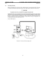
Test all outlets in the area for proper wiring arrangement by plugging in the neon outlet tester and
noting the combination of lights that are illuminated (Illustration 3-1). Any problems found should
be reported to the hospital immediately and the receptacle should not be used.
The Dale 600 has self-contained lamps designed for testing the outlet wiring arrangement. Plug the
Dale 600 into each outlet to be tested comparing the lamp status with Illustration 3-2.
NOTE:
No outlet tester can detect the condition where the white neutral wire and the green
grounding wire are reversed. If later tests indicate high leakage currents, this should be
suspected as a possible cause and the outlet wiring should be visually inspected.
Illustration 3-1 Outlet Test
Illustration 3-2 Outlet Test—Dale 600
3-2-3
Type CF Applied Part Leakage Current Limits—Surgical Transducers and ECG
Connections
Country
Normal Condition
Open Ground Reverse Polarity
Open Neutral
*Mains Applied
USA
0.01 mA
0.01 mA
0.01 mA
0.01 mA
0.02 mA
Other
0.01 mA
0.05 mA
0.05 mA
0.05 mA
0.05 mA
*
Mains Applied refers to the sink leakage test where mains (supply) voltage is applied to the part to
determine the amount of current that will pass (or sink) to ground if a patient contacted mains voltage.
Summary of Contents for LOGIQ 200
Page 4: ......
Page 8: ......
Page 10: ...05 23 00 MAC Page 2 of 2 ...
Page 28: ...05 23 00 MAC Page 2 of 2 ...
Page 87: ...LOGIQ α200 ...
Page 88: ...LOGIQ 200 PRO ...
Page 144: ......
Page 190: ......
Page 196: ......