


GE MEDICAL SYSTEMS
LOGIQ 200 PRO Series PROPRIETARY MANUAL
2242594
DIAGNOSTICS
2--20
REV 0
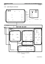
2--3--2 System Diagnosis (Continued)
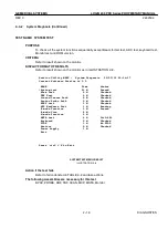
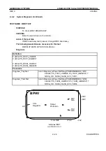
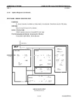
TEST NAME: BEAM FORMER TEST
PURPOSE
To check Beam Former and analog processing part.
CRITERIA
--.There are 8 images in beam former test that called image 0 ~image 7. It is possible to change by
focusing selection keys.
--.Two images (Image=0 and Image=1) are only used for system diagnostics (Image=2~7: Re-
served).
--.Grey line that spread a boundary and not perceived clearly, as a grey line.
--.Black line that draw a clear black line in the test image.
--.Pair that consisted of two lines. Each line viewed apart from the other.
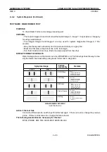
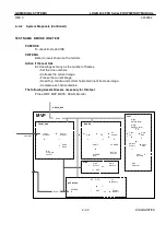
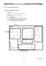
DISPLAY FORMAT OF RESULTS
Refer to image shown on the monitor as in ILLUSTRATION 2--9. The following shows the way to clas-
sify the failure board assembly using beam former test in diagnostic.
Symptom Image
Failure
Assembly
Remark
Image=0
Image=1
--SCAN Assy
--TBF Assy
--RBF Assy
--Probe Channel
--Nothing
--.Pair
--.Image=0: Black line
--.Image=1: Gray line
--.Position Remained
--.No Pair
--.Image=0: Gray line
--.Image=1: Gray line
--.Position moved
--.Pair
--.Image=0: Black line
--.Image=1: Black line
--.Position Remained
(Same Brightness)
--.No Pair
--.Image=0: Black line
--.Image=1: Gray line
--.Position Remained
--.Normal
--.No lines in image=0 and
Image=1
BEAM FORMER TEST MENU
ILLUSTRATION 2--9
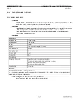
Action if the test fails
Connect a different probe, and then perform this test again. If there is no error, change the previous
probe. If there is still some error, change the failure board.
The following Assemblies are necessary for this test
BPHV, PROBE, RBF, TBF, SCAN, MVP, MSTE, Monitor
Summary of Contents for LOGIQ 200
Page 4: ......
Page 8: ......
Page 10: ...05 23 00 MAC Page 2 of 2 ...
Page 28: ...05 23 00 MAC Page 2 of 2 ...
Page 87: ...LOGIQ α200 ...
Page 88: ...LOGIQ 200 PRO ...
Page 144: ......
Page 190: ......
Page 196: ......