background image

85

Basic Operation

3. Within 30 nautical miles of KTOP, the 

GNS 480 switches from en route mode 

to terminal mode and the CDI scale 

transitions from 2.0 to 1.0 nautical 

miles, full scale deflection. 

4. As you approach the IAF (

LEBVY

), a 

waypoint message (“LEFT TO TRK 

352°”) appears on the bottom of 

the screen. As the distance to the IAF 

approaches zero, the message begins to 

count down to the turn 10 seconds prior 

to initiating the turn. 

5. Follow the arc and keep the CDI needle 

centered. When using a non-roll steering  

autopilot, the course select on the CDI 

(or HSI) must be periodically updated 

with the desired track (DTK) to ensure 

proper tracking through the arc. If 

you are using a roll steering-capable 

autopilot which will fly the arc automatically. If you are vectored to intercept the arc, press the 

Direct-

To

 key, highlight the waypoint D025G with the 

Large

 key which has a small arc symbol above it. Press 

the 

FlyLeg

 menu item key to make the arc leg guidance active on the CDI. 

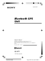
6. The next point in the approach is an intermediate fix, labeled “DMARY.” As you approach this 

intermediate fix, a waypoint message (“RIGHT TRK 205°”) appears on the bottom of the screen. As the 

distance to this fix approaches zero, the message is replaced by a 10 second countdown message prior 

to the turn. 

7. Dial this course into the CDI (or HSI) using the OBS knob and initiate a standard rate turn to this course 

heading. 

DMARY

LEBVY


DO NOT USE FOR  

NAVIGATION

Billard Muni (Topeka, KS) 

VOR or GPS Rwy 22

Procedures

Summary of Contents for GNS 480

Page 1: ...DRAFT GNS 480TM color GPS WAAS NAV COM pilot s guide ...

Page 2: ...to a hard drive or other electronic storage medium to be viewed and to print one copy of this manual or of any revision hereto provided that such electronic or printed copy of this manual must contain the complete text of this copyright notice and provided further that any unauthorized commercial distribution of this manual or any revision hereto is strictly prohibited Information in this document...

Page 3: ...ation packet is included in your GNS 480 package Pilots using an out of date database do so entirely at their own risk CAUTION GPS receivers operate by receiving and decoding very low power radio signals broadcast by satellites It is possible that in some situations other radio equipment or electronic equipment used in close proximity to a GPS receiver may create electromagnetic interference EMI w...

Page 4: ...lot s Guide and Quick Reference Guide GNS 480 Interactive Training CD Database Subscription Packet Warranty Registration Card GPS Antenna kit is available as a separate option selected at the time of order Your Garmin dealer will perform the installation and configuration of your new GNS 480 After installation the NavData card will already be installed into the unit The GNS 480 will be secured in ...

Page 5: ...eration chapter provides you with information about basic features such as using the Moving Map Com and Nav radios navigating a route and using waypoints There are also step by step directions to assist you in these operations The Appendix contains information such as specifications optional accessories and maintenance information You can also find warranty safety and FCC information in the Append...

Page 6: ...ap Mode Menu Items 21 GNS 480 Map Mode Nav Data Options 22 Basic Operation 24 Nav HSI Display NAV 31 Panning PAN 33 Range 33 Create a New User waypoint 33 Direct To 34 ActFP 34 DB 34 Direct 34 Inserting a Hold at a Waypoint in the Active Flight Plan 35 Destination Dest 35 Course To CrsTo 36 Course From CrsFr 36 OBS 37 OBS to a Waypoint in Your Flight Plan 37 OBS to a Waypoint Not in Your Flight Pl...

Page 7: ... for Setting Up a Simple Flight Plan 62 Steps for Setting Up a Flight Plan Using Terminal Procedures and Airways 62 A Set Origin Destination and Alternate Waypoints 63 B Add a Standard Instrument Departure SID Procedure 63 C Insert En Route Flight Plan Airways and or Waypoints 64 D Modifying a Flight Plan While In Flight 64 E Add Arrival Procedures STARS 65 F Add Approach Procedures 65 LEG TYPES 6...

Page 8: ...20 Manual Track 120 Present Position PPOS 121 Airspeed 121 Messages MSG 122 Text Messages 122 Audio Messages 126 Setting Message Audio Level 127 Traffic TFC 128 Traffic Display Range Ring 128 Traffic Symbols 128 Traffic Pop Up 129 No Bearing Traffic Advisories Skywatch Only 129 Vertical Display Modes 130 Operate Standby 130 Test 130 Traffic in Map Mode 131 Traffic Annunciations 131 Specifications ...

Page 9: ... WAAS navigator and transpon der controller all in a single unit The GNS 480 CNX80 with the GPS WAAS navigator is certified for use as primary navigation equipment for both VFR and IFR operations This Pilot s Guide covers the details so you can get the most out of your GNS 480 CNX80 quickly For more details and examples refer to the GNS 480 CNX80 Computer Based Training CBT compact disc and in fli...

Page 10: ...ccess more features VOR Select Nav radio mode Press VOR The function and menu item smart keys access more features XPDR Select the External Transponder mode if installed Press XPDR The function and menu item smart keys access more features CDI Toggles the main CDI output between GPS and internal VOR LOC radio sources SUSP Manually suspends or resumes flight plan waypoint sequencing When waypoint s...

Page 11: ...eated waypoints Flight Service Station FSS with frequency data and Air Route Traffic Control Center ARTCC with frequency data The function and menu item smart keys access more features INFO Activates Info mode for the highlighted waypoint or the active flight plan ActFP waypoint Informa tion about the selected waypoint such as location name a map frequencies and more depending on the waypoint type...

Page 12: ...he next area to edit with the Large knob If you are in Map mode pressing the CRSR activates PAN mode In Transponder mode it allows editing squawk codes In Direct To and Flight Plan FPL modes activating the CRSR control will help narrow a waypoint search Datacard The Map database and other information is stored on a data card The use of a data card allows you to easily update information NOTE Only ...

Page 13: ...cription of common elements are shown below When you press the COM VOR or XPDR keys on the left side of the display the window for that function will be outlined and the information active for editing will be highlighted The labels for the bottom row of Function smart keys will change for each function selected Press Menu Enter to display Menu Item smart keys The Menu Item smart keys will adjust t...

Page 14: ...tomatically decluttered to remove map detail for clarity as you increase the map range 1 Press MAP to reach Map mode Radio Nav Transponder CDI Annunciator or pilot customized information is shown on the left side of the display and the map display is shown on the right side 2 There are four Map pages that you select by turning the Large knob 3 Turn the Small knob to change the Map range Map pages ...

Page 15: ...the Left NDB Flight Plan Waypoint Arc to the Right User Waypoint Intersection Left Procedure Turn Inbound Entering Procedure Turn Left Left Hand Holding Pattern Inbound Entering Procedure Turn Right Direct To Left Hand Holding Pattern Outbound Right Hand Holding Pattern Outbound Right Hand Holding Pattern Inbound The following symbols are used on the map display to depict active legs of flight way...

Page 16: ...8 Getting Started ...

Page 17: ...9 Getting Started ...

Page 18: ...10 Getting Started ...

Page 19: ...hen GPS approach is active and on Final Approach course i e VTF or FAF MAP or the first Missed Approach waypoint is active CDI resolution is variable for all approaches and becomes more sensitive as you near the runway LOI LOI Loss of Integrity appears on the left side of the map display when WAAS GPS is unable to calculate the integrity of the position or calculated integrity is insufficient to s...

Page 20: ...g CDI Window HDG xx Displayed when a PILOT NAV Heading Leg is the active flight plan leg The current head ing is shown If heading information is not available the field is dashed CDI Window PILOT NAV Guidance is not provided on this leg by the GNS 480 Use other flight instruments to fly this leg TFC TFC Fail TFC STBY TFC Test TFC N A Status of the external traffic source LPV LP Lnav Vnav Lnav Lnav...

Page 21: ...proper operation You may press SKIP to bypass the startup tests however completing these tests is required for IFR flight Any failures will be noted by a message Set Fuel Full and Reserve If a Fuel Air Data Computer is installed Fuel Full and Fuel Reserve amounts are entered manually in the Con figuration page of System mode and are reflected in the start up screens On start up you will be prompte...

Page 22: ...cklist page View Messages You can review system messages by pressing the MSG function smart key Turn the Large knob to switch between New and Old messages Turn the Small knob to scroll through the available messages The Message annunciator M will flash until all unread messages have been read While old messages exist and there are no new messages the Message annunciator will remain solid The Messa...

Page 23: ...er to view options Controls and features may vary depending on the transponder Press the Emrgncy menu item key and then Menu Enter to insert the 7700 squawk code Press the VFR menu item key to insert the 1200 squawk code Press the TrgrSpd menu item key to select the speed that will trigger the automatic activation of the transponder SL70 only when in Auto mode 1 Turn the Large and Small knobs to s...

Page 24: ...16 Getting Started Nav Terms Diagram Flight Plan Terms Diagram ...

Page 25: ...mall knobs to select the Origin waypoint and then press Menu Enter 4 Use the Large and Small knobs to select the Destination waypoint and then press Menu Enter This allows you to select the appropriate terminal procedures from the database The active flight plan is deleted and is replaced with the new Direct To flight plan 5 Highlight the departure waypoint and insert a waypoint or airway Continue...

Page 26: ... or press INFO to display information about that waypoint 6 Press the RAIM function key to perform a RAIM prediction Find a Nearest Waypoint Frequency 1 Press NRST and then press the menu item key for the desired waypoint type Turn the Large knob to highlight the desired waypoint 2 If the desired frequency is shown in the Nearest list press the Standby SBY or Active A smart keys to insert the freq...

Page 27: ... to accept the procedure 6 If desired select an alternate airport by pressing the Alternate Select menu item key 7 Press EXEC to activate the procedures for your flight plan Perform a RAIM Prediction RAIM prediction predicts if GPS coverage is available for any waypoint This is used when WAAS satellites or corrections are not available If WAAS corrections are not available vertical guidance will n...

Page 28: ...isplay is shown on the right side 2 There are four Map pages that you select by turning the Large knob 3 Turn the Small knob to change the Map scale Map pages 2 4 allow you to customize the Nav display items on the left side of the display and map display detail 4 Press Menu Enter to view the Menu items for the choices to customize your display 5 Press the key next to the Menu item to control the ...

Page 29: ...isplayed A thin outline means that airspaces will not be displayed on the map Traffic Toggles on off the display of traffic when it is installed Flight Plan Map pages 2 4 Toggles display of route line on off Declutter Auto Declutter Toggles decluttering of the display of labels and icons on off at the higher zoom levels Nav Data Sel Data Customize the Nav information on map pages 2 4 Press the Nav...

Page 30: ...ge knob to select pages 2 4 You can t change the Nav information options for page 1 3 Press the Menu Enter key 4 Press the More selection key until the Nav Data selection is available 5 Press the Nav Data menu item key 6 Press the Sel Data menu item key to activate selection of options of Nav Data information 7 Turn the Large knob to highlight the desired Nav Data item Turn the Small knob to chang...

Page 31: ...e resolu tion Cabin Pressure Cab Prs The current cabin pressure value when an external carbon monoxide is installed Not selectable if CO Guard ian is not configured Note Cabin pressure alerting is not supported Feet ft or meters m in whole units Cabin Temperature Cab Tmp The current cabin temperature value when an external carbon monoxide is installed Not selectable if CO Guard ian is not configur...

Page 32: ...nd minutes 00 00 to 23 59 based on a 24 hour clock Estimated Time En Route to Final Destination Dest ETE The estimated time en route to the final destination waypoint using the same information as the Dest ETA field except it is calculating the time en route If the active leg is not part of the flight plan ie direct to outside the flight plan ground speed is less than or equal to five knots or pos...

Page 33: ... waypoint If the current leg is a pilot nav leg or heading to manual termi nation then the distance is dashed If the position is invalid then the distance is dashed Nautical miles nm statute miles sm or kilometers km 0 00 to 9 99 units at 0 01 unit resolution 10 0 to 99 9 units at 0 1 unit resolu tion and 1 unit resolution otherwise Distance to Destination DIST TO Dest This is the distance to the ...

Page 34: ...ve knots or position is invalid this will be dashed Hours and minutes 00 00 to 23 59 based on a 24 hour clock Estimated Time En Route ETE The estimated time remaining en route to the active waypoint It does not give consideration for a curved path If the active leg is a pilot nav leg or to a manual termination unless FM or HM leg ground speed is less than or equal to five knots or posi tion is inv...

Page 35: ...maining from the initial fuel entered at start up subtracting fuel used Value is dashed out when fuel used information is not available Not selectable if Fuel or FADC is not configured 0 0 to 99999 9 US gallons usg Im perial gallons img liters L pounds lbs or kilograms kg at tenths of unit resolution Estimated Fuel to Final Destination FUEL TO Dest The estimated fuel used to reach the final destin...

Page 36: ...e GPS ALT If available this provides GPS altitude referenced to MSL Note that this altitude will not be the same as baro corrected altitude when airborne Feet ft or meters m in whole unit resolution GPS Vertical Rate GPS VS If available this provides GPS based vertical speed Feet minute ft m or meters minute m m Shall support at least range of 9999 units to 9999 units Value shall be rounded to 10 ...

Page 37: ...his requires an FADC or CO Guardian input Degrees Celsius ºC True Airspeed TAS The true airspeed is only available if an air data computer is providing it Value is dashed out otherwise Knots kt kilometers per hour k h or miles per hour m h 0 to 999 units at 1 unit resolution Track Angle Error TKE The Track Angle Error TKE is the difference between the aircraft s track and desired track TKE is foll...

Page 38: ... or arrow oriented for the wind with the wind speed to the right Value is dashed out if not avail able or unable to calculate internally Knots kt kilometers per hour k h or miles per hour m h 0 to 999 units at 1 unit resolution Cross Track Error XTE This is straight line distance Value is dashed out if position is invalid Nautical miles nm statute miles sm or kilometers km 0 00 to 9 99 units at 0 ...

Page 39: ... on the left side of the display When vertical guidance is provided a vertical deviation indicator is shown on the left side of the display The CDI VDI is driven by one of the following GPS data if GPS CDI annunciation is selected or Nav radio data if LOC VOR or ILS annunciation is selected Nav Mode HSI Display With VDI The Nav HSI function is useful for aircraft with auto pilots that do not have ...

Page 40: ...ction A white triangle above the center of the HSI points in the same direction of the CDI arrowhead if the CDI is in the To state The white triangle will be below the center of the HSI and point in the opposite direction of the CDI arrowhead if the CDI is in the From state LPV LP Lnav Vnav or Lnav annunciations are centered and appear below the compass rose when these ap proaches are active The a...

Page 41: ... the crosshair cursor position from your present position and the Lat Lon of the crosshair position is shown at the bottom of the map display Range Press the Range key to highlight the Range menu item When Range is selected turning the Small knob will change the map range to zoom in or out at the crosshair position Create a New User waypoint User waypoints allow you to create unique waypoints not ...

Page 42: ...ect course to the displayed waypoint 1 When you press Direct To the default waypoint shown will be the highlighted waypoint in your flight plan unless another waypoint is highlighted in another operation then that waypoint would be used You can turn the Large knob to select a different leg in your flight plan 2 You may select a waypoint that is not in your flight plan by pressing the DB key and th...

Page 43: ...he holding pattern based on the selected inbound course When you near the holding pattern flight plan sequencing is suspended Press SUSP SUSP annunciator will turn off to exit the holding pattern and return to the flight plan Roll steering capable autopilots may fly the hold entry and pattern automatically Destination Dest The Dest menu item smart key replaces the active flight plan with a direct ...

Page 44: ...sTo A map is displayed showing the selected course 3 Change the course bearing if desired Turn the Large knob to change the value in 10 increments Turn the Small knob to change the value in 1 increments 4 Press Menu Enter Course From CrsFr The Course From operation allows you to navigate from a waypoint on a pre defined course The default course for the Course From operation will depend on whether...

Page 45: ...nt position OBS to a Waypoint in Your Flight Plan If the OBS waypoint is on the map display a magenta line will be drawn for the Course To After you intercept that line the GNS 480 will track the course inbound to the selected OBS fix The white line on the Map is the Course From the OBS fix Once the aircraft intercepts the OBS course the GNS 480 will fly the course in bound and then continue outbo...

Page 46: ...e FlyLeg function FlyLeg With the FlyLeg Menu selection you can activate a particular leg of your flight plan This feature allows you to bypass a leg in your flight plan This is useful when you are vectored onto an airway If you have picked a leg that cannot be activated for navigation a message will appear to advise you Press CLR to exit 1 Press Direct To 2 Select the desired leg of your flight p...

Page 47: ... the Large knob to highlight green the waypoint you want to select Search Around a Reference Point SRCH Search for the 20 nearest items from a selected waypoint in your flight plan FP or in the database DB Nearest Frequency While viewing the Nearest waypoints that have frequency information you can transfer the displayed frequen cy to the Active or Standby frequency The GNS 480 automatically knows...

Page 48: ...o insert the frequency into the Active position Info on Nearest Waypoint 1 Press NRST 2 Press the key for the waypoint type you want to search 3 Turn the Large knob to select the nearest waypoint 4 Press the INFO button Fly Direct To a Nearest Waypoint 1 Press NRST 2 Press the key for the waypoint type you want to search Press More to view more types 3 Turn the Large knob to scroll thru the list o...

Page 49: ...cted waypoint Pressing the Dest key will erase the active flight plan and build a one leg flight plan direct from your present position to the new destination airport This makes the arrivals and approaches available for the new destination airport 6 Press PROC 7 Press Appch for the destination waypoint Select the approach with the Large and Small knobs You can also select the type of approach with...

Page 50: ... Other map datums are noted as unknown unk When viewing information that contains Com or VOR frequencies pressing the SBY or A keys will insert the highlighted frequency into the appropriate radio Airport Information Identifier city facility name state country elevation type map datum and fuel Position bearing and distance from present position sunrise sunset in UTC lat lon coordinates and magneti...

Page 51: ...me of operation bearings runways and other comments The Freq key will now be half highlighted 3 Turn the Large knob to scroll through the list of frequencies for that airport while still displaying the extra information Blue arrows on the right side of the display will show the direction where more frequencies are available 4 Press the Freq key again to return to the frequency list Info Mode Airpo...

Page 52: ... VOR Map of area NDB Information Identifier city state country bearing and distance from present position frequency lat lon coordinates and magnetic variation Map of area Airway Intersection Information Identifier country bearing and distance from present position lat lon coordinates and magnetic variation Map of area Info Mode Airway Intersection Info Mode NDB Info Info Mode VOR Information ...

Page 53: ...on is used when you are operating outside of areas served by WAAS coverage or if WAAS is unavailable Use the results of the calculation to verify signal integrity 1 While in INFO mode press the RAIM smart key when it is shown 2 Press the CRSR knob in One of the fields will be highlighted Change the values of the Arrival Date and or Arrival Time in UTC time with the Small knob while moving to a val...

Page 54: ...function When Monitor mode is active the MON annunciator will appear on the left side of the standby frequency and the MON function label will be highlighted Frequency monitoring allows you to listen to the Standby frequency while the GNS 480 moni tors the Active frequency for activity When the Active frequency receives a signal you will hear the Active frequency until its activity stops The frequ...

Page 55: ...n t normally need to use these values 1 Press Menu Enter and then the Signal key The Signal menu label will be highlighted 2 Press the Signal key again to turn the value display off Weather The GNS 480 holds a list of Weather frequencies that can be placed in the Active or Standby position for lis tening You may not transmit on a Weather frequency Weather frequencies are not available in some loca...

Page 56: ...ss Menu Enter and then the Audio key to bring up the Audio Level values The Audio menu label will be highlighted 2 Press the Audio key again to turn the value display off 3 Turn the Large knob to highlight the Audio Message Annunciator AMA volume Com radio volume Sidetone level and Nav radio volume 4 Use the Small knob to adjust the values Save Channel This function allows you to save and name the...

Page 57: ...r is not in the list no distance will be provided No distance will be shown for a localizer that does not have a collocated DME ID Press the ID key to toggle the Nav audio between Voice or ID After pressing the ID key and the ID function label is highlighted the Morse ID will be available When the ID function label is not highlighted Nav audio Voice is selected Monitor MON Press the MON key to tog...

Page 58: ...toggle between the display of the ID Identifier To radial or From radial values Back Course When the Active frequency is an ILS the Back Course mode will be available for ILS frequencies Press Menu Enter and then the Back CRS key to turn Back Course mode on Back Course mode reverses needle sensing When on the Back CRS menu label will be highlighted and the BC annunciator will appear When you are u...

Page 59: ...ibrated source or unit Ground means the unit was calibrated while on the ground Air means the unit was calibrated while in the air 6 Turn the Large knob to move to the Location selection Press the Cursor knob in to start editing Turn the Small knob to change the character Turn the Large knob to the next character and turn the Small knob to change the character When editing is complete press the Cu...

Page 60: ... place the transponder in Standby mode No information will be transmitted while in Standby mode A SBY annunciator will appear to the left of the squawk code ON Press the ON key to enable Mode A operation An ON annunciator will appear to the left of the squawk code ALT Press the ALT key to enable Mode C S operation which also sends altitude data along with your squawk code An ALT annunciator will a...

Page 61: ...y Auto mode is active when it is highlighted Press Auto again when you want to deactivate the Auto mode Flight ID For GTX33 330 installations the Flight ID can be either tied to the tail number of the aircraft set at installa tion time or set to another value by the flight crew as needed The Flight ID key allows you to either just view the Flight ID or view and edit the Flight ID For installations...

Page 62: ...termination Manually Select a Squawk Code 1 Press the CRSR in or turn the Large knob to activate squawk code editing Numbers 0 7 will be displayed adjacent to the Smart and Line Selection keys 2 Press the key for the desired number After pressing a numbered key the next number to the right will be active for editing or 1 Change the number value with the Small knob and move to the next number with ...

Page 63: ...th the Active plan highlighted the menu items are View Reverse Save or Edit If you press the CLR key you will be prompted to verify that you want to clear all information out of the Active plan which is the same as cancelling your flight plan The Active plan is cleared of all information but the Library flight plan of that name is not changed Modified Flight Plan The Modified flight plan is a temp...

Page 64: ... separate from the Active flight plan The Comment CMNT menu item allows you to add a line of text below the flight plan name Flight Plan Functions The function and the menu item smart keys adjust to reflect the appropriate commands for the flight plan or operation you are viewing View Displays the active flight plan Back Press the BACK function smart key to return to the previous display No change...

Page 65: ...noted as Remote The Remote flight plans exist as part of the library of flight plans shared by the two units The units do not share the Active flight plan used for navigating unless Cross Link X Link is activated When the units are powered on they synchronize their flight plans and User waypoints The unit with the most recent flight plans and User waypoints will take precedence and replace the pla...

Page 66: ...sert another Waypoint or press the Arwy key to insert an Airway 4 After modifying the flight plan the smart keys give you the choice of Back Executing or Expanding and viewing details in the new Flight Plan Execute Exec Use the Execute command to make the highlighted flight plan the Active flight plan A flight plan that is being modified will not be used until you press Exec and confirm the activa...

Page 67: ...cessary to remove the discontinuity immediately At some point in the flight the pilot needs to fill in the information needed to complete the flight plan and remove the discontinuity If the discontinuity is not removed disco will be displayed on the bottom of the map display for the next and then the active legs as a reminder to correct the flight plan If you fly into a discontinuity the flight pl...

Page 68: ...ct by Waypoint Type a With the first character of the Identifier highlighted press the CRSR knob in The whole Identifier field will be highlighted Now turn the Large knob counter clockwise CCW one turn to highlight the waypoint type field b Turn the Small knob to display the different waypoint types 5 Select by Facility Name a With the first character of the Identifier highlighted press the CRSR k...

Page 69: ...he Origin or Dest or Alternate menu item smart keys to change these waypoints 5 The flight plan is renamed and shown in the Library by the new Origin and Destination waypoint names 6 Press the SAVE function smart key to save the flight plan Inserting a Waypoint or Airway in Your Flight Plan 1 Highlight a waypoint with the Large knob 2 Press the Wpt menu item smart key to insert another waypoint 3 ...

Page 70: ...he identifier facility name city or waypoint type 3 Select the Origin waypoint as described in Edit a Flight Plan above Press Menu Enter 4 Select the Destination waypoint Press Menu Enter 5 Select the final operation for creating this flight plan Save or Execute Press SAVE to store the flight plan in the Library for future use or press EXEC to both save the Library plan and make the plan the Activ...

Page 71: ...ow be displayed Select the Destination waypoint and press Menu Enter 4 Set an Alternate airport if desired Turn the Large knob CCW to highlight the flight plan name Press the Altrnt key and select an alternate airport waypoint along the flight plan with the Large and Small knobs The alternate airport will be added in parentheses to the flight plan name 5 Press SAVE B Add a Standard Instrument Depa...

Page 72: ...ay be modified in either the Flight Plan FPL or Procedure PROC modes In Flight Plan mode you can modify the entire flight plan In Procedure mode you can modify procedures for the Origin and Desti nation airports Both methods are shown below Using Flight Plan Mode to Modify a Flight Plan 1 Press the FN key and then the FPL key 2 If necessary highlight the Active flight plan Press the EDIT key 3 If ...

Page 73: ...in the Destination section 2 Use the Large and Small knobs to select the runway arrival and transition 3 Press Menu Enter F Add Approach Procedures 1 Press the Appr key Select the approach with the Large and Small knobs or the keys on the right side of the display Press Menu Enter 2 Press the XPND Expand key to view all waypoints and legs in the flight plan Every waypoint airway procedure and inte...

Page 74: ...s are allowed below 400 feet AGL for an instrument departure Upon reaching the required altitude the GNS 480 will sequence automatically to a heading to intercept leg of 120 to the 166 course to UBG The heading leg of 120 is shown as a Pilot Nav leg and sequencing may be accomplished by pressing the SUSP key once Once the flight plan sequences the guidance to the 166 course will be active on your ...

Page 75: ...LOT NAV The heading to a DME distance leg defines a heading to fly and a DME distance at which the leg terminates The distance is defined by both the identifier of the DME fix and the distance The pilot will have to maintain the desired heading manually and initiate sequencing manually upon reaching the specified DME distance PILOT NAV The heading to an intercept leg defines a heading to intercept...

Page 76: ...y and initiate sequencing manually when appropriate The heading to an altitude leg defines a heading to fly and an altitude at which the leg sequences The pilot will have to maintain the desired heading manually but sequencing to the next leg in the flight plan happens automatically upon reaching the specified altitude The course to a fix leg defines a path to a fix on a specific course When a cou...

Page 77: ...ed by both the identifier of the DME fix and the distance as shown in the example the Course To is C238 and the Identifier is VIL with the DME distance of 0 70 nm is shown in brackets The pilot will have to maintain the desired course manually and initiate sequencing manually upon reach ing the specified DME distance PILOT NAV The course to an intercept leg defines a specific course to be flown fr...

Page 78: ...d radial This can be easily accomplished using the VOR receiver The constant radius arc leg is similar to an arc to a fix leg This leg can occur at any location and will define an arced path between two other legs Also unlike the arc to a fix leg there should be no separate turn required at the beginning or end of this type of leg You may fly this leg keeping the CDI centered as you fly the curved...

Page 79: ... left or right to initiate the turn A maximum distance in which the turn must be accomplished is also defined and drawn on the moving map This type of leg is always followed by a course to a fix leg that establishes the inbound course after the turn is completed The direct to a fix leg allows navigation directly to a database fix from your present position When direct to navigation is initiated by...

Page 80: ...to be flown and an altitude at which the holding pattern is to be terminated This leg is most often used in a departure where a certain altitude must be attained in a hold before continuing en route Hold to an Altitude The hold to a manual termination leg defines a holding pattern to be flown for an indefinite number of turns These can be added using the Hold function under the Direct To key They ...

Page 81: ...ix at which the leg terminates The pilot will have to maintain the desired course manually and initiate sequencing manually upon reaching the specified distance from the fix PILOT NAV The fix to a DME distance leg defines a specific course to be flown away from a database fix and a DME distance at which the leg terminates Since the leg does not necessarily start at the DME the distance is defined ...

Page 82: ...ate sequencing manually when appropriate If this fix to manual termination leg was initiated by the pilot using the course from function under the Direct To key then sequencing will not be allowed The arc to a fix leg is used to define a DME arc leg A DME distance and the terminating fix are used to define this leg This leg is typically used in VOR DME approaches The GNS 480 provides guidance on c...

Page 83: ...ve between fields and the Small knob to scroll through the available procedure choices A representative map is shown below the procedure name 5 You can press the BACK function smart key to back up to the main Procedure page without making any changes 6 Press Menu Enter to select the procedure This inserts it into the Modified Flight Plan and proceeding to Flight Plan Edit mode for review and execu...

Page 84: ...he GNS 480 displays and guides you through each leg of the approach automatically sequencing through each of these legs up to the missed approach point MAP Approaches may be flown as published with the full transition using any published feeder route or initial approach fix IAF or may be flown with a vectors to final transition Approach operations on the GNS 480 typically begin with the same basic...

Page 85: ...ical miles away you select the ATIS frequency to monitor airport conditions and runway usage This is accomplished by displaying the INFO Page and selecting the ATIS frequency from the list Press SBY to place the frequency on standby Use the COM monitor function to listen to the ATIS frequency Your active frequency will not be affected 2 From ATIS you learn that runway 04 is in use and plan your ap...

Page 86: ...tely one minute past the IAF LYH the message LEFT TO TRK 164 appears on the bottom of the screen You may initiate the procedure turn at any time after receiving this alert message 5 Turn left to a heading of 160 to initiate the procedure turn Course guidance is provided relative to the outbound leg from the FAF The procedure turn is displayed on the Map Page and indicated as the active leg on the ...

Page 87: ...m of the display RIGHT TO TRK 025 appears Make any course adjustments necessary for the final course segment FAF to MAP 10 As you cross the FAF the destination sequences to the MAP RW04 the runway threshold With the needle centered fly toward the MAP observing the altitude minimums dictated by the approach plate 11 As you cross the MAP you will receive an audio message missed approach point unless...

Page 88: ...ial from LYH VOR The leg for the 010 heading will sequence automatically after reaching the appropriate altitude The heading leg for the 080 heading will suspend Establish the airplane on a 080 heading as required Once established press the SUSP key once to cause the GNS 480 to sequence to the next leg When the 053 course comes alive complete the intercept manually or automatically using the autop...

Page 89: ...ern at the IAF BODRY intersection 4 Press PROC and select the GPS 21 approach 5 From the transitions window select the BODRY intersection as the IAF Review the loaded approach and select Execute EXEC to activate the approach When cleared select Direct To BODRY 6 As in the last example within 30 nautical miles of the airport the GNS 480 switches from en route mode to terminal mode and the CDI scale...

Page 90: ...by going around the holding pattern again press SUSP to manually suspend waypoint sequencing BEFORE crossing the holding waypoint the second time 9 At 2 0 nautical miles from the FAF DEPOY intersection the GNS 480 switches from terminal mode to approach mode CDI scaling is tightened from either 2 or 1 0 to 0 3 nautical mile full scale deflection whichever is smaller 10 As you approach the FAF a wa...

Page 91: ...D APPROACH POINT Follow the missed approach instructions The GNS 480 will sequence to the first leg of the missed approach procedure which is a course of 209 to 2600 feet It will then automatically sequence direct to BODRY for holding once the altitude requirement is met Fly the guidance shown on the GNS 480 to the hold DO NOT USE FOR NAVIGATION Procedures The circle at the end of a leg indicates ...

Page 92: ...wing to intercept the arc Fly direct to the IAF on the DME Arc Follow ATC vectors which allow you to intercept the arc at any point along the arc If so use the Flyleg function in Direct To to activate the DME Arc leg This example is based upon a flight from Hutchinson Kansas Municipal KHUT to Billard Municipal KTOP in Topeka Kansas The VOR DME runway 22 ap proach is selected along with LEBVY as th...

Page 93: ... through the arc If you are using a roll steering capable autopilot which will fly the arc automatically If you are vectored to intercept the arc press the Direct To key highlight the waypoint D025G with the Large key which has a small arc symbol above it Press the FlyLeg menu item key to make the arc leg guidance active on the CDI 6 The next point in the approach is an intermediate fix labeled DM...

Page 94: ...yed in magenta the active leg of the flight plan always appears in magenta and a dashed magenta line shows the first leg of the missed approach 10 As you approach the MAP a waypoint message with countdown time appears on the bottom of the screen 11 The Missed Approach consists of a course to altitude leg of 214 to an altitude of 1281 feet Press the CDI key to switch the CDI source from the VOR bac...

Page 95: ...or course reversal in holding is selected and ATC subsequently vectors you to the final approach course VTF mode will automatically remove the procedure turn and make the in bound course active for the intercept To select VECTORS from the transitions field 1 Press the PROC key and select the VOR 22 approach 2 From the transitions field select VECTORS 3 Review the modified flight plan and execute i...

Page 96: ...ode and the CDI scale transitions from 2 0 to 1 0 nautical miles full scale deflection 2 If you haven t already done so activate VTF mode and set the inbound course on the CDI This allows the GNS 480 to guide you to the final approach course Verify that VTF is annunciated 3 ATC instructs you to turn left to a heading of 025 This places you parallel to the final approach course in the opposite dire...

Page 97: ...to MAP 8 As you cross the FAF the destination sequences to the MAP RW22 With the needle centered fly toward the MAP observing the altitude minimums dictated by the approach plate 9 As you approach the MAP a waypoint message appears on the bottom of the screen and an audio message occurs 10 See the Flying the Missed Approach In VTF mode if you are within 45 of the inbound course and you are on the ...

Page 98: ...nm of cross track error 5 there are no course reversals in the flight plan to be performed and 6 the ILS frequency is valid with a decoded ident The illustration shows both multiple locations along the approach path and the CDI selection that you can ex pect GPS or VLOC Within the area of the shaded box the automatic switch from GPS to VLOC should occur The pilot will receive a message SWITCHING F...

Page 99: ...rom the transitions field select SHUTR as the IAF Review and execute the modified flight plan Go direct to SHUTR when cleared for the approach 4 When you Execute an ILS approach the ILS frequency is automatically checked If the correct frequency is not in the active field you will receive a message informing you of the correct frequency Press Menu Enter to put the frequency into the active field o...

Page 100: ... from en route mode to terminal mode and the CDI scale transitions from 2 0 to 1 0 nautical miles full scale deflection 2 As you approach the IAF SHUTR a waypoint message LEFT TO TRK 030 appears on the bottom of the screen 3 Verify that the ILS frequency ident has been automatically decoded on the display 4 As the distance DIS to the IAF approaches zero the message is replaced by a turn advisory t...

Page 101: ...ars in the lower right corner of the screen CDI coupling automatically switches from the GPS receiver to the VLOC receiver as you complete the inbound turn If the ILS frequency has not been tuned this automatic CDI switch does not occur NOTE From this point on primary naviga tion is provided by the VLOC receiver You may continue to use the GPS receiver for supplemental navigation guidance only If ...

Page 102: ... is displayed in magenta the active leg of the flight plan always appears in magenta 13 As you approach the MAP a waypoint message NEXT CRS 210 appears on the bottom of the screen 14 At the DH DA initiate the missed approach if necessary Once the GNS 480 crosses the MAP Defined as the runway end waypoint the GNS 480 will autoswitch back to GPS data NOTE If you have turned autoswitch off press the ...

Page 103: ...6 The GNS 480 will automatically sequence upon reaching the required altitude Direct To FLG for the missed approach hold Continue to fly the CDI needle guidance and the missed approach hold as described earlier Procedures ...

Page 104: ...AF LOTKE the GNS 480 will begin to automatically rescale in an angular fashion This will allow the LPV approach to be flown in the same fashion as a standard localizer approach similar to an ILS This is true for both the lateral and glidepath guidance At 2 0 nautical miles from the FAF CDI scaling is tightened from either 2 or 1 0 to 0 3 nautical miles full scale deflection whichever is smaller 5 ...

Page 105: ...ned as the runway end waypoint the GNS 480 will automatically sequence to the first leg of the missed approach NOTE For missed approaches with heading legs fly manually until the first active course leg is reached as described in earlier sections 11 Fly the guidance provided by the GNS 480 to the ARTTY intersection and hold Flying the LP Approach An LP approach is flown the same as an LPV approach...

Page 106: ...this approach In the rare event the GPS HAL limits cannot meet non precision limits the GNS 480 will notify the pilot with a message to abort the approach The GNS 480 will revert to terminal limits of 1 0 NM to support navigation to the missed approach 6 As you cross the FAF the destination sequences to the MAP the runway threshold With the needle on the external CDI or HSI centered fly toward the...

Page 107: ...pproach plates and vastly improve situ ational awareness throughout the approach However you must always fly an approach as it appears on the approach plate The active leg or the portion of the approach currently in use is depicted in magenta on the bottom of the Map or Flight Plan pages As you fly the approach the GNS 480 automatically sequences through each leg of the approach unless suspended t...

Page 108: ... the autopilot coupled you must monitor system functions at all times and verify that the autopilot and external CDI or HSI switch to the VLOC receiver with sufficient time to capture and track the approach course Switching to VLOC late in the ap proach may not provide the autopilot enough time to respond and intercept the approach course prior to the FAF depending upon the performance characteris...

Page 109: ...approach with automatic CDI switching disabled 1 You may select LOC guidance at any point on the approach prior to reaching the FAF 2 The localizer frequency must be active to use LOC guidance Course Transitions Greater Than 270 For procedures that have heading or course changes in excess of 270 degrees roll steering will not be available until you have passed the point where a turn less than 270 ...

Page 110: ... and Timer 2 Edit the Timer values by pressing in the CRSR knob move the cursor with the Large knob change the value with the Small knob and then press the Enter key Press the 1 Min or 2 Min keys to instantly insert one or two minutes as the time Press the Disp key to display the Timer value on the Map pages The Disp key will be highlighted and an asterisk will appear next to the value that will b...

Page 111: ... stop after the aircraft has been below the Trigger Speed for 30 seconds or more Trigger Speed Set the Trigger Speed for the speed where you want the Flight Time and Distance counters to start and stop 1 Turn the Large knob to highlight Trigger Speed 2 Press the CRSR knob in The Trigger Speed will now be highlighted 3 Turn the Small knob to the desired speed and then press the CRSR knob again or p...

Page 112: ...t result for that item Turn the Small knob to choose the desired checklist result See the following table for available checklist results If you want to make your own result press the CRSR knob in and use the Small and Large knobs to name the new result Press Menu Enter when finished 6 Turn the Large knob to the next checklist item Continue with the process in the previous steps until finished wit...

Page 113: ...cklist 1 Press FN and then the CHK key to start the Checklist function 2 Press the MOV key 3 Turn the Large knob to the position in the order of lists where you want to put the highlighted list and press the Menu Enter key Checklist ...

Page 114: ...Electric Trim Engine Instruments Environmental System Flaps Flight Controls Flight Data Recorder Fuel Control Heat Fuel Generators Inverter Inverters Landing Gear Handle Lights Strobes Lights Mags O2 Control Pressure Oil Pressure Overspeed Governors Papers Parking Brake Power Levers Primary Governors Prop Feather Prop Sync Propeller Levers Radar Rotating Beacon Stabilizer Trim Takeoff Briefing Tra...

Page 115: ...TH CHECK ON CHECKED CHECKED AS REQD CHECKED OFF CHECKED OUT CHECKED SET COMPLETE CUT OFF DOWN EXCERCISED FEATHER FREE CORRECT FULL RICH HI RPM IDLE LO IDLE LOW RPM NORMAL NS FSB OFF OFF AS REQD ON ON CHECKED OPEN REVIEWED SET SET PRESS TESTED CLEAR UP Checklist ...

Page 116: ... 2 Press the NEW or EDIT key 3 Use the Small and Large knobs to name or edit the waypoint name You can also set a range and bearing from a reference waypoint 4 Turn the Large knob to go to each field on the page and edit the values 5 Press Menu Enter when finished Searching for a User Waypoint 1 Press FN and then the USER key to start the User Waypoint function 2 Press the SEARCH key 3 Use the Sma...

Page 117: ...setting or the use of SBAS is prohibited for the selected approach Time Current UTC time computed from the GPS constellation EPU Estimated Position uncertainty in meters Dashes are shown if the value is not valid HPL Horizontal Protection Level in meters Dashes are shown if the value is not valid VPL Vertical Protection Level in meters Dashes are shown if the value is not valid Lat Lon Current pos...

Page 118: ... the value range can be set between 27 00 and 34 99 If pressure is in millibars the value range can be set between 914 and 1117 This is not required for installations with barometric altimeter inputs The GNS 480 will prompt you for the values if an input is not available 1 Turn the Large knob to highlight the Baro Correct selection 2 Press the CRSR knob in to start editing 3 Turn the Small knob to...

Page 119: ...rn the Large knob to highlight the magnetic variation degrees selection 2 Press the CRSR knob in to start editing 3 Turn the Small knob to change the value 4 Press the CRSR knob in again or press the Menu Enter key to save the value CDI Scale The maximum CDI scale deflection can be set CDI scaling is used to allow the CDI needle to be more sensi tive and prevent scalloping or slalom tracks for cer...

Page 120: ...to display distance information in units of nautical miles nm kilometers km or statute miles sm 1 Turn the Large knob to highlight the Distance Units selection 2 Press the CRSR knob in to start editing 3 Turn the Small knob to change the value 4 Press the CRSR knob in again or press the Menu Enter key to save the value Altitude Units This selection allows you to display altitude information in uni...

Page 121: ...mperial Gallons IMG Liters L Pounds LBS Kilograms KG 1 Turn the Large knob to highlight the Baro Pressure selection 2 Press the CRSR knob in to start editing 3 Turn the Small knob to change the value 4 Press the CRSR knob in again or press the Menu Enter key to save the value Fuel Full Amount Set the amount of fuel when the aircraft fuel tanks are full in the currently selected fuel units 1 Turn t...

Page 122: ...er key to save the value Display Brightness Selection Select between Automatic and Manual Display Brightness Automatic Display Brightness is controlled by the ambient light readings by a photosensor on the front panel The Manual Display Brightness selection allows you to control the display brightness with the Power Volume knob 1 Turn the Large knob to highlight the Display Brightness selection 2 ...

Page 123: ...nd then setting this value so the ding volume is adequate 1 Turn the Large knob to highlight the Message Tone selection 2 Press the CRSR knob in to start editing 3 Turn the Small knob to change the value 4 Press the CRSR knob in again or press the Menu Enter key to save the value Airspace Alerts The Airspace Alerts selection allows you to turn Airspace Alerts on or off When alerts are turned on a ...

Page 124: ...present the aircraft as it appears on the Map display Choices include Single Twin Jet or Helicopter 1 Turn the Large knob to highlight the Aircraft Icon selection 2 Press the CRSR knob in to start editing 3 Turn the Small knob to change the value Use the Large knob to move the cursor 4 Press the CRSR knob in again or press the Menu Enter key to save the value VFR Squawk You may store the frequency...

Page 125: ...manually enable or disable WAAS Normally WAAS should be enabled but there are some situations where it is useful to dis able it when required by local regulatory agencies 1 Turn the Large knob to highlight the Enable WAAS selection 2 Turn the Small knob to change the value 3 Press the Menu Enter key to save the value Entering Owner Information ...

Page 126: ...r flight plan will automatically cancel Parallel Track Parallel track is cancelled if a course change occurs greater than 120 or the parallel tracks overlap as a result of the course change Activating Parallel Track 1 Press FN and then the PTK key to reach the Parallel Track function 2 Press the CRSR knob 3 Turn the Small knob to change the value for the Distance parallel from the flight track Wit...

Page 127: ...allel Track Description When Parallel Track is Activated p is added to the waypoint names in the From To Next line at the bottom of the map and on the waypoints shown on the map The PTK annunciator is shown in the left corner of the screen ...

Page 128: ...e using the Simulator 1 After the GNS 480 start up screen clouds and title ends and the left side of the display information just appears press SUSP three times 2 Press Menu Enter to continue in Simulator mode or press CLR to continue with normal operation 3 Turn the Small knob if desired to change the Local Altimeter Setting Press Menu Enter to continue to the start up test phase Press SKIP to by...

Page 129: ...he displayed values or press CLR to cancel the selection and return to the previous display Airspeed The Airspeed SPD key brings up a display where you can select the Track Speed and Altitude 1 Turn the Large knob to select the item to change 2 Turn the Small knob to change the values 3 Press Menu Enter to accept the displayed values or press CLR to cancel the selection and return to the previous ...

Page 130: ...ress the MSG key 3 Turn the Large knob or press the New or Old keys to switch between the Old and New Messages 4 Turn the Small knob to list the available New or Old messages Text Messages Message Description Inside of x Within x nm of SUA Within x min of SUA Special Use Area alert Pilot awareness of upcoming pilot action required For Loaded Approach Do NOT use GPS For Primary Navigation Guidance ...

Page 131: ... changes are allowed Altitude Out of Range Check Altitude Encoder Pilot awareness Check unit prior to next flight CAUTION Altitude Encoder Communications Failure Altitude information is not being received by the GNS 480 CAUTION Fuel Air Data Communications Failure Fuel Air Data Computer information is not being received by the GNS 480 CAUTION Fuel Data Communications Failure Fuel Data sensor infor...

Page 132: ...Failure Pilot awareness CAUTION Unable to Command Transponder Pilot awareness Active Flight Plan Memory Loss Reload flight plan and activate as required Initiating Auto Track Mode Following Flight Plan Simulator mode only Initiating Manual Track Using Manual Track Speed and Altitude Simulator mode only Steep Turn Ahead or others Pilot awareness Arrival or Arrival in x sec Pilot awareness Pilot Nav...

Page 133: ...ked on power up System configuration invalid See dealer or call Customer Service Config Error Verify User Settings Go to System Configuration page and check user set tings CDI Selection Should be set To Localizer ILS or VOR Pilot awareness Standby VOR Frequency Set To xxx xx For Approach ENTER Flip to Active Pilot awareness Database Invalid Database needs updating Database unavailable until update...

Page 134: ...OC or GPS CDI autoswitching is taking place Modified Flight Plan Has Not Been Executed CAUTION Traffic Source Data Failure Communication lost with data source CAUTION Transponder Failure Traffic Failure Communication lost with GTX33 330 Configured for TIS Non WGS 84 waypoint navigation Pilot awareness CAUTION Fuel Data Communications Failure Communication lost with data source Audio Messages The G...

Page 135: ...on of 90 or less Missed Approach when flying an approach and the MAP has been passed an audio message will occur once The Missed Approach message will not be played for an ILS or LPV approach unless the LPV approach has been downgraded If audio is inhibited the audio alert messages are not played Audio messages do not require any pilot input Message tones can be turned on or off through the system...

Page 136: ...pop up screen will appear on any other page when a traffic advisory condition occurs The Map display can also be configured to add traffic as an overlay with the other map selections Traffic Display Range Ring Range rings are used to display relative distances on the display The current range values are shown on the lower left edge the rings The range is changed by turning the Small knob At the 2 ...

Page 137: ...uder has no computed bearing and is a Traffic Advisory The message will appear as amber text in the lower center right of the display and includes range and altitude with the vertical arrow if altitude is available An example message would read TA 1 2 12 for a threat that is 1 2 nm away and 1200 feet above your position and descending at a rate greater than 500 fpm A no bearing advisory that has a...

Page 138: ... the Menu Enter key 2 Pressing the Vert key will step through the available choices The label for the currently selected view will be displayed in the upper left corner Operate Standby Use this function to toggle the Traffic information display between Operational OPER and on Stand By STBY The current state is shown in the upper right corner of the display 1 Press Menu Enter 2 Press Stby or Oper t...

Page 139: ... not been received for 6 12 seconds RMVD 0 30 RMVD 0 30 TIS only annunciations Traffic is removed from the display This mes sage is displayed when data has not been received for 13 59 seconds After 60 seconds the message will transition to TFC Unavailable TFC N A Not Available TIS only annunciations Aircraft is outside the TIS coverage area TFC STBY Standby Traffic is in Standby state Set Traffic ...

Page 140: ...136 975 MHz Transmit Power 8 watts minimum at 12 VDC VOR Performance Frequency Range 108 00 MHz to 111 75 MHz Localizer Performance Frequency Range 108 00 MHz to 111 95 MHz Glideslope Performance Frequency Range 329 150 MHz to 335 00 MHz Specifications Physical Specifications Size 6 25 W x 3 3 H x 11 7 D 15 9 x 8 4 x 29 7 cm Weight 5 8 lbs 2 6 kg unit only 0 7 lbs 0 3 kg mounting tube Display 3 8 ...

Page 141: ...ed the battery should be replaced within 1 to 2 months If the battery is not replaced and becomes totally discharged the GNS 480 will remain fully operational but the GPS signal acquisition time will be increased This acquisi tion time can be reduced by entering a new seed position each time the unit is powered on There is no loss of function or accuracy of the GNS 480 with a dead battery The batt...

Page 142: ...t is not necessary to force the card The handle is still exposed when it is properly inserted DO NOT insert or remove the data card while the unit is powered on If you insert a data card and get a card format not recognized message try removing the card and reinserting it If the card is still not recognized contact the Garmin or your Garmin dealer for assistance Data cards are not waterproof shoul...

Page 143: ...st Street Olathe KS 66062 3426 USA Phone 913 397 8200 FAX 913 397 8282 http www garmin com Be prepared to offer the following information about the installation Installation configuration list of any accessories Model number part number with mod levels and serial number Software Versions Description of problem Efforts made to isolate the problem Contacting the Factory ...

Page 144: ...nce you are off a desired course in either direction left or right Decluttering Reduction in displayed elements on the moving map at higher zoom scales Distance Destination The great circle distance from current location to a Go To destination or the final waypoint in a route Distance Next The great circle distance from current location to a Go To destination or the next waypoint in a route ETA De...

Page 145: ...ecified on the VNAV screen Glideslope HIWAS Hazardous Inflight Weather Advisory Service Max Speed The maximum speed the unit has moved Mode A Transponder mode only reporting the squawk code Mode C Transponder mode reporting squawk code and altitude Mode S Transponder mode reporting squawk code altitude and supports selective aircraft interroga tion Next Course The remaining distance of the route N...

Page 146: ...imer Moving Time the unit has been moving since last reset of the trip timers Trip Timer Total Total time the unit has been in operation since last reset of the trip timers Turn The angle difference in degrees between the bearing to your destination and your current line of travel L means turn Left R means turn Right User Timer Display the user timer set in the Main Menu Velocity Made Good The spe...

Page 147: ...used on the GNS 480 and their mean ings ABV Above ACTFP Active Flight Plan ACTV Active ALT Altitude APPR APPCH Approach APT Airport ARTCC Air Route Traffic Control Center ARWY Airway ATC Air Traffic Control ATK Automatic Track AUX Auxiliary AVGAS Aviation grade Gasoline BARO Barometric Pressure BRG Bearing To BLW Below C Degrees Celsius CAS Calibrated Airspeed CCW Counter Clockwise CDI Course Devi...

Page 148: ... Hold to Manual Leg HPL Horizontal Protection Level HSI Horizontal Situation Indicator IAF Initial Approach Fix ID IDNT IDENT Identifier ILS Instrument Landing System IMC Inclement Meteorological Conditions img Imperial Gallons IND Indicated INT Intersection INTEG Integrity kg Kilograms kHz Kilohertz km Kilometers kph Kilometers Per Hour kt Knots LAT LON Latitude Longitude lb Pounds LCL Local LFOB...

Page 149: ...Turn Required NRM Normal NRST Nearest OBS Omnibearing Selector ppm Parts per million PPOS Present Position PROC Procedure s PTK Parallel Track PWR Power RAD Radial RAIM Receiver Autonomous Integrity Monitoring RCL Recall REF Reference REQ Required Requirements RESTRICTD Restricted RMVD Removed RNAV Area Navigation RNG Range RX Receive SBAS Space Based Augmentation System SEL Select SID Standard In...

Page 150: ...tricted usg US gallons UTC Coordinated Universal Time also GMT or zulu VDI Vertical Deviation Indicator VERS Version VFOM Vertical Figure Of Merit VFR Visual Flight Rules VHF Very High Frequency VLOC VOR Localizer Receiver VNAV Vertical Navigation VOL Volume VOR VHF Omnidirectional Radio Range VPL Vertical Protection Level VS Vertical Speed VTF Vector To Final WAAS Wide Area Augmentation System WN...

Page 151: ...f WAAS for the most accurate location fix Safety Information WARNING The GNS 480 contains a lithium ion rechargeable battery The battery used in this device may present a risk of fire or chemical burn if mistreated Do not recharge out of the unit disassemble heat above 140 F 60 C or incinerate WARNING If original battery must be removed for replacement dispose of used battery properly Contact your...

Page 152: ...interference to radio communications However there is no guarantee that interference will not occur in a particular installation If this equipment does cause harmful interference to radio or television reception which can be determined by turning the equipment off and on the user is encouraged to try to correct the interference by one of the following measures Reorient or relocate the receiving an...

Page 153: ...e export the Software to any country in violation of the export control laws of the United States of America Product Registration and Support Help us better support you by completing your online registration today Have the serial number of your GNS 480 handy and connect to the Garmin Web site www garmin com Look for the Product Registration link on the home page Also be sure to record your serial ...

Page 154: ... PRODUCT Some states do not allow the exclusion of incidental or consequential damages so the above limitations may not apply to you Garmin retains the exclusive right to repair or replace the unit or software or offer a full refund of the purchase price at its sole discretion SUCH REMEDY SHALL BE YOUR SOLE AND EXCLUSIVE REMEDY FOR ANY BREACH OF WARRANTY To obtain warranty service call your local ...

Page 155: ...6 C Cards 134 Care Information 133 Cautions i CDI 2 CDI Scale 111 Checklist 14 104 Cleaning 133 Clear 3 Comment 58 Com Radio 2 14 46 Configuration 110 Contacting Factory 135 Controls 2 Copy 58 Course 136 Course From 36 Course To 36 Cross Link 57 Cursor 4 D Data Card 4 13 134 Data Fields 136 DEST 35 Direct To 3 17 34 DIRECT TO 65 Discontinuity 59 Display 5 Brightness 114 Distance Units 112 DME 49 D...

Page 156: ... Distance 137 O OBS 37 Owner Information 116 P Pan Mode 33 Range 33 Parallel Track 118 Pilot Nav Leg 59 Power 2 Present Position 121 Procedure 19 75 Turn 77 78 Product Support 145 R RAIM 19 45 Recall 46 50 Registration 145 Remote 57 Reverse 57 S Safety Information 143 Save Channel 48 50 SBAS 117 Self Test 13 Serial Number 145 Signal 47 Simulator 120 Skywatch 129 Slave 120 Software Version 109 Spec...

Page 157: ... Final 75 80 87 Velocity Made Good 138 Vertical Speed 138 VFR Squawk 116 VOR 44 VPL 12 32 109 142 W WAAS 117 143 Wide Area Augmentation System 143 Warranty 146 Waypoint User 108 Waypoint Information 3 42 Weather 47 X X Link 57 XPDR 52 ...

Page 158: ...150 Index ...

Page 159: ......

Page 160: ...Street Olathe Kansas 66062 U S A Garmin Europe Ltd Liberty House Bulls Copse Road Hounsdown Business Park Southhampton SO40 9RB U K Garmin Corporation No 68 Jangshu 2nd Road Shijr Taipei County Taiwan www garmin com Garmin AT Part Number 560 0984 01 Rev D Garmin P N 190 00502 00 Rev B ...

Reviews: