190-02692-00 Rev. A
Garmin G100 Pilot’s Guide for the Piper PA-32 Saratoga
54
FLIGHT INSTRUMENTS
SY
STEM
O
VER
VIEW
FLIGHT
INSTRUMENTS
EIS
AUDIO P
ANEL
& CNS
FLIGHT
MANA
GEMENT
HAZARD
AV
OID
ANCE
AFCS
ADDITIONAL FEA
TURES
APPENDICES
INDEX
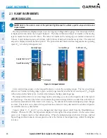
Figure 2-11 Horizontal Situation Indicator (360˚ HSI)
1
10
11
14
12
15
9
3
4
2
8
9
7
5
1
Turn Rate Indicator
2
Current Track Indicator
3
To/From Indicator
4
Navigation Source
5
Aircraft Symbol
6
Course Deviation Indicator
(CDI)
7
Rotating Compass Card
8
OBS Mode Active
9
Lateral Deviation Scale
10
Flight Phase
11
Course Pointer
12
Heading Bug
13
Turn Rate and Heading Trend
Vector
14
Current Heading
15
Lubber Line
6
13
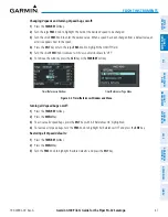
The Arc HSI is a 140˚ expanded section of the compass rose. The Arc HSI contains a Course Pointer,
combined To/From Indicator and a sliding deviation indicator, and a deviation scale. Upon station passage, the
To/From Indicator flips and points to the tail of the aircraft, just like a conventional To/From flag. The Course
Pointer is a single line arrow (GPS, VOR1, and LOC1) or a double line arrow (VOR2 and LOC2), depending on
the navigation source, and points in the direction of the set course.
Lateral
Deviation
Scale
Course
Deviation
and To/From
Indicator
Figure 2-12 Arc HSI
Course Pointer
Navigation
Source
Flight Phase
Track Indicator
The selected heading is shown to the upper left of the HSI for three seconds after being adjusted. The cyan
heading bug on the compass rose corresponds to the selected heading. While the HSI is displayed as an arc, if
the heading bug is adjusted off the shown portion of the compass rose, the digital reading is displayed.


