Revision 1
44
6/27/2017
Output Parameter Radio Buttons –
Use the “Next Field” and “Previous Field” buttons on the
keypad to select the parameter to be assigned to the analog output.
Track or Hold –
Use the “Next Field” and “Previous Field” buttons on the keypad to navigate
to the “Track” or “Hold” field and press enter to place an “X” beside the desired output
behavior. Select “Track” if the output is to be updated when the analyzer is in back purge or
performing a zero calibration. Select “Hold” if the output is to hold the last valid reading while
the analyzer is in back purge or performing a zero calibration.
Full Scale –
Enter the value of the desired full scale for the output.
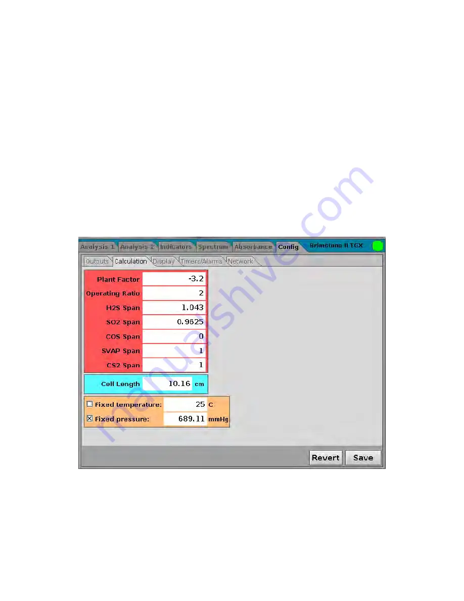
4.8.2 Calculation Sub-Panel
The
Calculation
sub-panel (Figure 4-10) is used to set a broad range of calibration
parameters.
Figure 4-11: Calculation Sub-Panel
To edit a parameter, use the
Field Prev
or
Field Next
button to access the field and press
Enter. A dialog box similar to Figure 4-6 will be presented. Enter the desired value, select the
Okay button and press
Enter
.
When all desired changes have been made, select Save. Selecting Revert will keep the
parameter values that were used before the start of the editing process.
Summary of Contents for 943-TGS
Page 50: ...Revision 1 50 6 27 2017 Figure 4 14 Network Sub Panel ...
Page 94: ...Revision 1 94 6 27 2017 Figure 9 1 Mounting Detail ...
Page 95: ...Revision 1 95 6 27 2017 Figure 9 2 Oven Cabinet Detail ...
Page 96: ...Revision 1 96 6 27 2017 Figure 9 3 Control Cabinet Detail ...
Page 97: ...Revision 1 97 6 27 2017 Figure 9 4 Power Air Steam Requirements and Input Output Detail ...
Page 98: ...Revision 1 98 6 27 2017 Figure 9 5 Control Cabinet to Oven Cabinet Interconnect Detail ...
Page 99: ...Revision 1 99 6 27 2017 Figure 9 6 AC Wiring Detail ...
Page 100: ...Revision 1 100 6 27 2017 Figure 9 7 DC and Signal Wiring Detail ...
Page 101: ...Revision 1 101 6 27 2017 This page intentionally left blank ...


