23
VSS-V2 Technical Manual
A100K11209 v.1.3
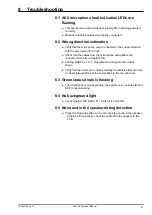
8 Troubleshooting
8.1 All 8 microphone fault indication LEDs are
flashing.
● This can be due to the microphone preamplifier not being powered
correctly.
●
Make sure that the cables are properly connected.
8.2 Wrong direction estimation
●
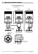
Verify that the microphone unit is connected in the correct direction,
with the part marked
F
in front.
● Check that the cables from the microphone preamplifier are
connected correctly to master PCB.
●
Cabling MUST be 1 to 1, otherwise the wrong direction will be
shown.
●
Verify that the unit is not in close proximity to obstacles that are able
to reflect large portions of the sound back to the microphones.
8.3 Green status diode is flashing
●
The microphone is not responding, the system is in override status or
DSP is not answering.
8.4 No background light
●
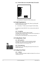
Check whether DIP switch S1 / switch 4 is set to ON.
8.5 No sound in the speaker during detection
●
Press the Override button to on and check the sound in the speaker.
-If there’s still no activity, check the cable from the speaker to the
PCB.
Summary of Contents for FA-150
Page 2: ...This page left intentionally blank ...
Page 4: ...This page left intentionally blank ...
Page 5: ...Revision history manual Rev A B C Description Date dd mm yyyy Sign A A 06 05 2015 HAB ...
Page 6: ...This page left intentionally blank ...
Page 8: ...This page left intentionally blank ...
Page 9: ...Index divider Section 1 N ...
Page 10: ......
Page 12: ...PRINTED IN JAPAN UAIS TRANSPONDER FA 150 ...
Page 53: ...Antenna Cable Set CP20 02700 004 381 160 CP20 02710 004 381 170 A 8 ...
Page 54: ...Antenna cable Set CP24 00300 000 041 938 CP24 00310 000 041 939 A 9 ...
Page 55: ...Y Hatai D 1 ...
Page 56: ...Y Hatai D 2 ...
Page 57: ...Y Hatai D 3 ...
Page 58: ...Y Hatai D 4 ...
Page 59: ...Feb 19 03 D 5 ...
Page 60: ...May 20 03 D 6 ...
Page 61: ...Feb 22 05 D 7 ...
Page 62: ...Jan 9 03 D 8 ...
Page 63: ...Mar 11 04 H Hayashi D 9 ...
Page 64: ...Feb 02 05 D 10 ...
Page 65: ...Nov 28 03 D 11 ...
Page 66: ...Oct 02 03 D 12 ...
Page 67: ...H Hayashi Mar 10 05 D 13 ...
Page 69: ...Index divider Section 2 N ...
Page 70: ......
Page 72: ...This page left intentionally blank ...
Page 129: ...Index divider Section 3 N ...
Page 130: ......
Page 187: ...Index divider Section 4 N ...
Page 188: ......
Page 190: ...TECHNICAL MANUAL A100K11209 v 1 3 Sound Reception System VSS V2 Installation User Manual ...
Page 204: ...15 VSS V2 Technical Manual A100K11209 v 1 3 4 7 Cable Connection Diagram ...
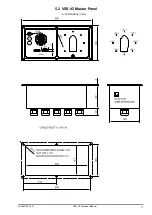
Page 206: ...17 VSS V2 Technical Manual A100K11209 v 1 3 5 2 VSS V2 Master Panel Dimensions in mm ...
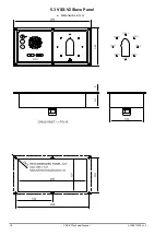
Page 207: ...18 A100K11209 v 1 3 VSS V2 Technical Manual 5 3 VSS V2 Slave Panel Dimensions in mm ...

