24
A100K11209 v.1.3
VSS-V2 Technical Manual
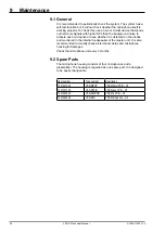
9 Maintenance
9.1 General
It is recommended to periodically check the system. The system has a
self-test function but it will not check whether the microphone itself is
working properly. To check this, use a horn or similar device that sends
out harmonic signals with higher SPL than the background noise to
activate each microphone to see whether it is detected on the diodes
and monitored in the internal loudspeaker of the master unit. It is also
recommended to visually check all terminal cables and microphone
housing for damages.
Check the microphone unit every 3 months.
9.2 Spare Parts
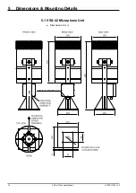
The microphone housing consists of four microphones and a
preamplifier. The housing is regarded as one spare part. It is designed
to be easily changeable.
Item number
Type number
Description
1021001020
VSS-MPCP
VSS Master PCB – V2
1021001030
VSS-SPCB
VSS Slave PCB – V2
1021002020
VSS-MICPCB
VSS Mic PCB – V2
1021002040
VSS-MIC
VSS Microphone – V2
Summary of Contents for FA-150
Page 2: ...This page left intentionally blank ...
Page 4: ...This page left intentionally blank ...
Page 5: ...Revision history manual Rev A B C Description Date dd mm yyyy Sign A A 06 05 2015 HAB ...
Page 6: ...This page left intentionally blank ...
Page 8: ...This page left intentionally blank ...
Page 9: ...Index divider Section 1 N ...
Page 10: ......
Page 12: ...PRINTED IN JAPAN UAIS TRANSPONDER FA 150 ...
Page 53: ...Antenna Cable Set CP20 02700 004 381 160 CP20 02710 004 381 170 A 8 ...
Page 54: ...Antenna cable Set CP24 00300 000 041 938 CP24 00310 000 041 939 A 9 ...
Page 55: ...Y Hatai D 1 ...
Page 56: ...Y Hatai D 2 ...
Page 57: ...Y Hatai D 3 ...
Page 58: ...Y Hatai D 4 ...
Page 59: ...Feb 19 03 D 5 ...
Page 60: ...May 20 03 D 6 ...
Page 61: ...Feb 22 05 D 7 ...
Page 62: ...Jan 9 03 D 8 ...
Page 63: ...Mar 11 04 H Hayashi D 9 ...
Page 64: ...Feb 02 05 D 10 ...
Page 65: ...Nov 28 03 D 11 ...
Page 66: ...Oct 02 03 D 12 ...
Page 67: ...H Hayashi Mar 10 05 D 13 ...
Page 69: ...Index divider Section 2 N ...
Page 70: ......
Page 72: ...This page left intentionally blank ...
Page 129: ...Index divider Section 3 N ...
Page 130: ......
Page 187: ...Index divider Section 4 N ...
Page 188: ......
Page 190: ...TECHNICAL MANUAL A100K11209 v 1 3 Sound Reception System VSS V2 Installation User Manual ...
Page 204: ...15 VSS V2 Technical Manual A100K11209 v 1 3 4 7 Cable Connection Diagram ...
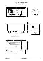
Page 206: ...17 VSS V2 Technical Manual A100K11209 v 1 3 5 2 VSS V2 Master Panel Dimensions in mm ...
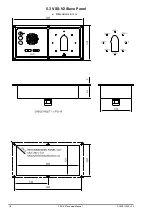
Page 207: ...18 A100K11209 v 1 3 VSS V2 Technical Manual 5 3 VSS V2 Slave Panel Dimensions in mm ...

