18
3. SETTING AND ADJUSTMENT
After installing the equipment, set up the own ship’s static information (MMSI, IMO
number, ship’s name, call sign, type of ship and GPS antenna position). Also, set
up the I/O ports.
3.1 Setting MMSI, IMO No., Name and Call Sign
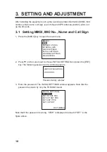
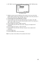
1. Press the [MENU] key to open the main menu.
[MENU]
MSG
SENSOR STATUS
INTERNAL GPS
USER SETTINGS
INITIAL SETTINGS
CHANNEL SETTINGS
DIAGNOSTICS
2. Press
ź
on the cursor pad to choose INITIAL SETTINGS and press the [ENT]
key. The following password entry window appears.
[ENTER PASSWORD]
Password entry window
3. Enter the password. The INITIAL SETTINGS window appears. Note that the
password is known by only the FURUNO dealer.
[INITIAL SETTINGS]
SET MMSI
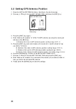
SET INT ANT POS.
SET EXT ANT POS.
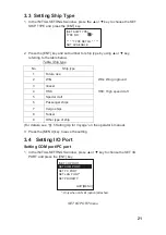
SET SHIP TYPE
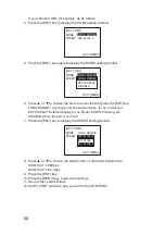
SET I/O PORT
QUIT [MENU]
SET MMSI
Note that if the password is wrong, “VIEW” is displayed in stead of “SET” in the
figure above.
Summary of Contents for FA-150
Page 2: ...This page left intentionally blank ...
Page 4: ...This page left intentionally blank ...
Page 5: ...Revision history manual Rev A B C Description Date dd mm yyyy Sign A A 06 05 2015 HAB ...
Page 6: ...This page left intentionally blank ...
Page 8: ...This page left intentionally blank ...
Page 9: ...Index divider Section 1 N ...
Page 10: ......
Page 12: ...PRINTED IN JAPAN UAIS TRANSPONDER FA 150 ...
Page 53: ...Antenna Cable Set CP20 02700 004 381 160 CP20 02710 004 381 170 A 8 ...
Page 54: ...Antenna cable Set CP24 00300 000 041 938 CP24 00310 000 041 939 A 9 ...
Page 55: ...Y Hatai D 1 ...
Page 56: ...Y Hatai D 2 ...
Page 57: ...Y Hatai D 3 ...
Page 58: ...Y Hatai D 4 ...
Page 59: ...Feb 19 03 D 5 ...
Page 60: ...May 20 03 D 6 ...
Page 61: ...Feb 22 05 D 7 ...
Page 62: ...Jan 9 03 D 8 ...
Page 63: ...Mar 11 04 H Hayashi D 9 ...
Page 64: ...Feb 02 05 D 10 ...
Page 65: ...Nov 28 03 D 11 ...
Page 66: ...Oct 02 03 D 12 ...
Page 67: ...H Hayashi Mar 10 05 D 13 ...
Page 69: ...Index divider Section 2 N ...
Page 70: ......
Page 72: ...This page left intentionally blank ...
Page 129: ...Index divider Section 3 N ...
Page 130: ......
Page 187: ...Index divider Section 4 N ...
Page 188: ......
Page 190: ...TECHNICAL MANUAL A100K11209 v 1 3 Sound Reception System VSS V2 Installation User Manual ...
Page 204: ...15 VSS V2 Technical Manual A100K11209 v 1 3 4 7 Cable Connection Diagram ...
Page 206: ...17 VSS V2 Technical Manual A100K11209 v 1 3 5 2 VSS V2 Master Panel Dimensions in mm ...
Page 207: ...18 A100K11209 v 1 3 VSS V2 Technical Manual 5 3 VSS V2 Slave Panel Dimensions in mm ...

