14
A100K11209 v.1.3
VSS-V2 Technical Manual
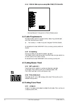
4.3.3 VSS-V2 Microphone Amplifier PCB ETC 600-870
• Terminal Block K1 Connection to VSS-V2 Master panel
4.4 Cable Requirements
All signal cables have to be approved ship cable of type twisted-pair
with outer braided copper shield.
L
See section
4.7 Cable Connection Diagram
for further details.
Terminal block marked “GROUND” is the common ground point for all
shields.
4.4.1 Grounding
Proper grounding is essential for reliable operation.
The shields must be interconnected in junction boxes and grounded in a
common point in the central unit only.
Terminal block marked “GROUND” is the common ground point.
4.5 Setting Master Panel
4.5.1 DIP switch S1
The DIP switch S1 (switch 4) enables and disables backlight
functionality. This switch must be set in default position ON.
The 3 other switches are for test purposes only.
4.5.2 Potentiometers
Potentiometer P1 is for VDR analog audio output. This must be set in
default middle position.
4.6 Setting Slave Panel
4.6.1 Jumpers
Jumper J3 enables and disables backlight functionality. This must be set
in default position ON.
Summary of Contents for FA-150
Page 2: ...This page left intentionally blank ...
Page 4: ...This page left intentionally blank ...
Page 5: ...Revision history manual Rev A B C Description Date dd mm yyyy Sign A A 06 05 2015 HAB ...
Page 6: ...This page left intentionally blank ...
Page 8: ...This page left intentionally blank ...
Page 9: ...Index divider Section 1 N ...
Page 10: ......
Page 12: ...PRINTED IN JAPAN UAIS TRANSPONDER FA 150 ...
Page 53: ...Antenna Cable Set CP20 02700 004 381 160 CP20 02710 004 381 170 A 8 ...
Page 54: ...Antenna cable Set CP24 00300 000 041 938 CP24 00310 000 041 939 A 9 ...
Page 55: ...Y Hatai D 1 ...
Page 56: ...Y Hatai D 2 ...
Page 57: ...Y Hatai D 3 ...
Page 58: ...Y Hatai D 4 ...
Page 59: ...Feb 19 03 D 5 ...
Page 60: ...May 20 03 D 6 ...
Page 61: ...Feb 22 05 D 7 ...
Page 62: ...Jan 9 03 D 8 ...
Page 63: ...Mar 11 04 H Hayashi D 9 ...
Page 64: ...Feb 02 05 D 10 ...
Page 65: ...Nov 28 03 D 11 ...
Page 66: ...Oct 02 03 D 12 ...
Page 67: ...H Hayashi Mar 10 05 D 13 ...
Page 69: ...Index divider Section 2 N ...
Page 70: ......
Page 72: ...This page left intentionally blank ...
Page 129: ...Index divider Section 3 N ...
Page 130: ......
Page 187: ...Index divider Section 4 N ...
Page 188: ......
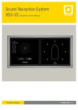
Page 190: ...TECHNICAL MANUAL A100K11209 v 1 3 Sound Reception System VSS V2 Installation User Manual ...
Page 204: ...15 VSS V2 Technical Manual A100K11209 v 1 3 4 7 Cable Connection Diagram ...
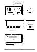
Page 206: ...17 VSS V2 Technical Manual A100K11209 v 1 3 5 2 VSS V2 Master Panel Dimensions in mm ...
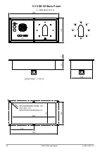
Page 207: ...18 A100K11209 v 1 3 VSS V2 Technical Manual 5 3 VSS V2 Slave Panel Dimensions in mm ...

