13
VSS-V2 Technical Manual
A100K11209 v.1.3
4.3 Terminals, Jumper and Potentiometer
Configurations
Pluggable screw terminals for cables of max. 2.5 mm
2
are utilized.
Refer to connection diagram for more detailed information.
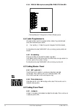
4.3.1 VSS-V2 Master Panel PCB ETC 600-868
• Terminal Block K1 VSS-V2 Microphone Unit
• Terminal Block K2 LED Indicators
• Terminal Block K3 Switch for muting Typhoon/foghorn
• Terminal Block K4 Audio out to Voyage Data Recorder (VDR)
• Terminal Block K5 - K8 VSS-V2 Slave Panels
• Terminal Block K9 24V Power supply
• DIP switch S1/4 Background Light On/Off
(S1/1-3 Internal use)
• Potentiometer P1 for adjusting VDR volume
4.3.2 VSS-V2 Slave Panel PCB ETC 600-869
• Terminal Block K1 Connection to VSS-V2 Master panel
• Jumper J2 Background Light On/Off
Summary of Contents for FA-150
Page 2: ...This page left intentionally blank ...
Page 4: ...This page left intentionally blank ...
Page 5: ...Revision history manual Rev A B C Description Date dd mm yyyy Sign A A 06 05 2015 HAB ...
Page 6: ...This page left intentionally blank ...
Page 8: ...This page left intentionally blank ...
Page 9: ...Index divider Section 1 N ...
Page 10: ......
Page 12: ...PRINTED IN JAPAN UAIS TRANSPONDER FA 150 ...
Page 53: ...Antenna Cable Set CP20 02700 004 381 160 CP20 02710 004 381 170 A 8 ...
Page 54: ...Antenna cable Set CP24 00300 000 041 938 CP24 00310 000 041 939 A 9 ...
Page 55: ...Y Hatai D 1 ...
Page 56: ...Y Hatai D 2 ...
Page 57: ...Y Hatai D 3 ...
Page 58: ...Y Hatai D 4 ...
Page 59: ...Feb 19 03 D 5 ...
Page 60: ...May 20 03 D 6 ...
Page 61: ...Feb 22 05 D 7 ...
Page 62: ...Jan 9 03 D 8 ...
Page 63: ...Mar 11 04 H Hayashi D 9 ...
Page 64: ...Feb 02 05 D 10 ...
Page 65: ...Nov 28 03 D 11 ...
Page 66: ...Oct 02 03 D 12 ...
Page 67: ...H Hayashi Mar 10 05 D 13 ...
Page 69: ...Index divider Section 2 N ...
Page 70: ......
Page 72: ...This page left intentionally blank ...
Page 129: ...Index divider Section 3 N ...
Page 130: ......
Page 187: ...Index divider Section 4 N ...
Page 188: ......
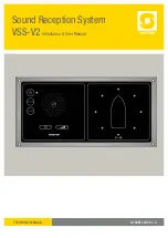
Page 190: ...TECHNICAL MANUAL A100K11209 v 1 3 Sound Reception System VSS V2 Installation User Manual ...
Page 204: ...15 VSS V2 Technical Manual A100K11209 v 1 3 4 7 Cable Connection Diagram ...
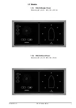
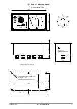
Page 206: ...17 VSS V2 Technical Manual A100K11209 v 1 3 5 2 VSS V2 Master Panel Dimensions in mm ...
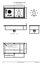
Page 207: ...18 A100K11209 v 1 3 VSS V2 Technical Manual 5 3 VSS V2 Slave Panel Dimensions in mm ...


