background image

55M3500AQE-C

55M3500AQE-C

WYLIE’s I3500 QuICk REfEREnCE shEEt

WYLIE’s I3500 QuICk REfEREnCE shEEt

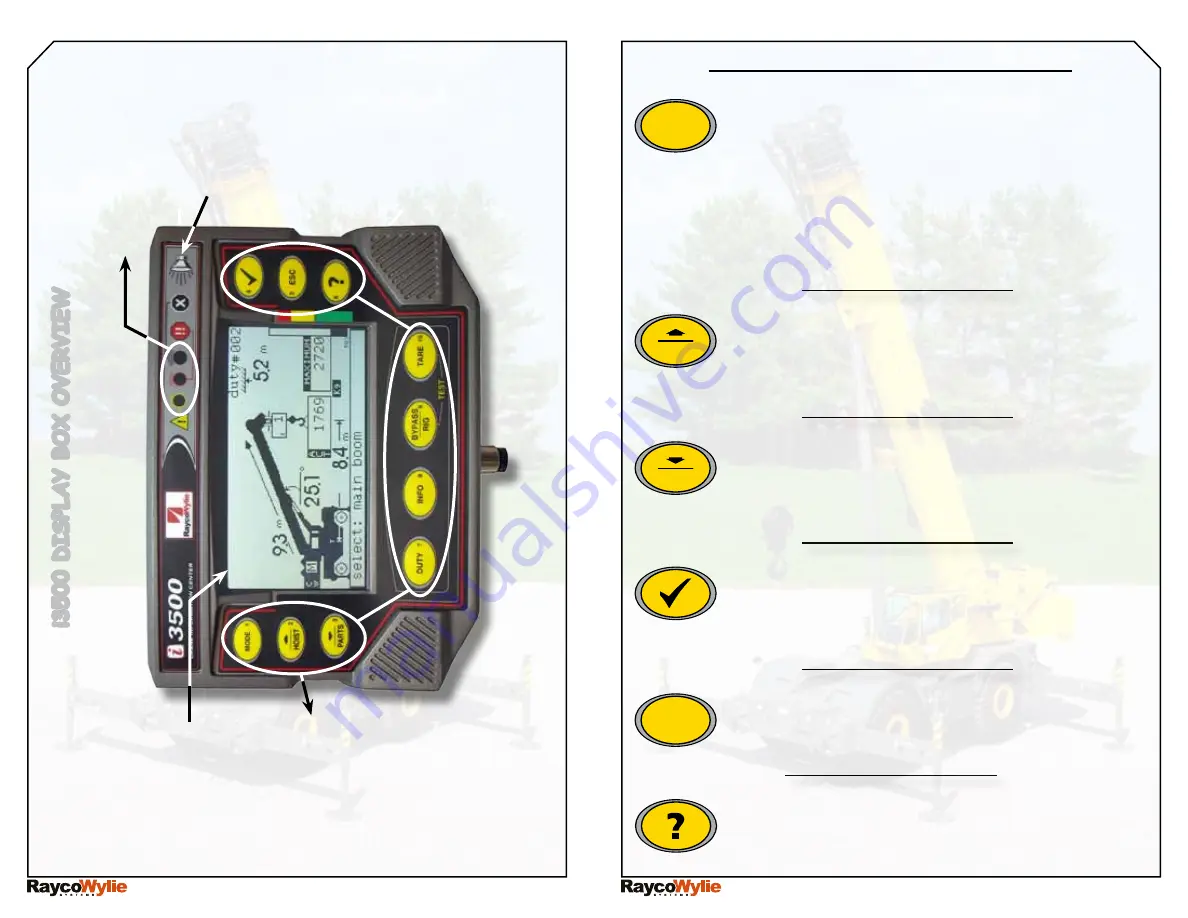
operating buttons presentation

Page 2

i3500 D

isp

La

bo

o

V

er

V

ie

W

operating buttons

W

arning Lig

H

ts

interna

bu

ZZ

er

grap

H

iC

a

L

D

isp

La

Y

Page 1

MODE BUTTON : Shows system’s modes. Press 

this  button  to  choose  one  of  these  operating 

modes:

-Normal mode

-Limits Setting or Range Limiting mode

-System Set Up mode

-Diagnostic mode

-Calibration mode (password protected).

MODE

1

Hoist / sCroLL up button : shows hoist menu 

for selection of the hoist currently in use. Also 

used  to  scroll  up  in  menus  or  increase  editable 

values.

HOIST

2

PARTS / SCROLL DOWN BUTTON : Shows parts 

of line (falls) menu for selection of the number of 

parts currently in use. Also used to scroll down in 

menus or decrease modifiable values.

PARTS

3

SELECT BUTTON : Used to select a highlighted 

item in a menu. In normal mode, use this button 

to select the information displayed in one of the 

pull down menus.

4

ESCAPE BUTTON : Used to close a menu or cancel 

the modification of a value. Push it several times 

to return to normal mode.

ESC

5

HELP BUTTON : This button will show the problem 

source when a fault is detected by the system. 

Push it to see a description of the problem.

6

Summary of Contents for i3500

Page 1: ...ion of the hoist currently in use Also used to scroll up in menus or increase editable values HOIST 2 PARTS SCROLL DOWN BUTTON Shows parts of line falls menu for selection of the number of parts curre...

Page 2: ...the boom length the head type and the counterweight DUTY 7 INFO BUTTON Shows all the information regarding the current crane configuration Push it a second time to access the operating system s inform...

Page 3: ...condition Hoist up telescope out and boom down functions will be stopped if a motion cut solenoid is connected to the system The overload warning light red in color illuminates at or above 100 of the...

Page 4: ...just there to remind you that an angle radius or height limit has been set in the limits setting mode This indicator appears on the screen when a preset maximum angle limit has been reached or is abo...

Page 5: ...she enters the crane and every time the crane is rigged Each hoist has its own configuration set up in memory Simply by changing the hoist from main to auxiliary the configuration and number of parts...

Page 6: ...number 57 represents your crane rigged with a 100 feet boomlength outriggers extended and with a 40 feet jib 10 it could be more convenient to input the number 57 instead of having to choose the corr...

Page 7: ...firm your choice 3 Boom up to the desired boom tip height limit 4 Push button 4 to confirm the maximum boom tip height position As you release button 4 an 8 second countdown will allow you to boom dow...

Page 8: ...rammed free zone limit becomes active 7 The display will automatically return to the normal mode Variable limit height 1 Access the range limiting mode see bottom of page 13 2 Use the down 3 button to...

Page 9: ...s will be the position of the first wall 6 Rotate the crane toward the second limit position second wall with the boom tip always at the maximum radius permitted by the surrounding environment 7 Push...

Reviews: