Index
C141-E224
IN-5
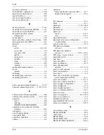
READ FP DMA QUEUED
command protocol ............................. 5-158
READ LOG EXT .................................. 5-131
READ LOG EXT log page 10h, data
format of .................................5-133, 5-134
READ MULTIPLE ................................. 5-77
READ MULTIPLE command,
execution example of ........................... 5-78
READ MULTIPLE EXT....................... 5-130
READ NATIVE MAX ADDRESS....... 5-120
READ NATIVE MAX ADDRESS
EXT.................................................... 5-129
READ SECTOR (S) EXT ..................... 5-127
READ SECTOR(S) ................................. 5-34
read segment buffer, using ...................... 6-16
READ VERIFY SECTOR (S) EXT...... 5-142
READ VERIFY SECTOR(S).................. 5-40
read/write circuit..........................2-3, 4-3, 4-9
read/write circuit block diagram................ 4-9
read/write preamplifier (PreAMP) ............ 4-9
read-ahead cache ..................................... 6-13
read-ahead cache system ........................... 1-3
RECALIBRATE ..................................... 5-33
recommended equipment........................... 3-8
recommended power-off sequence.......... 1-13
register - device to host ........................... 5-18
register - host to device ........................... 5-17
reliability ................................................. 1-11
reset ........................................................... 6-2
reset response .......................................... 6-21
reset, power-on and COMRESET ......... 5-160
response to COMRESET........................... 6-4
response to power-on................................. 6-2
response to software reset.......................... 6-7
restriction of use of hazardous
substance.............................................. 1-16
rewriting microcode data
(384 K bytes ), example of................... 5-46
ripple.......................................................... 1-6
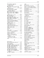
S
SATA interface.......................................... 2-3
SATA interface cable connection............ 3-11
sector count field ..................................... 5-25
sector number field.................................. 5-25
SECURITY DISABLE PASSWORD ... 5-118
SECURITY ERASE PREPARE ........... 5-114
SECURITY ERASE UNIT ................... 5-115
SECURITY FREEZE LOCK ................ 5-116
security password, content of ................ 5-118
SECURITY SET PASSWORD............. 5-110
SECURITY SET PASSWORD data,
contents of.......................................... 5-110
SECURITY UNLOCK.......................... 5-112
SEEK .......................................................5-42
seek operation ..........................................4-18
selective self-test feature flag...................5-71
selective self-test log data structure .........5-70
selective self-test pending time [min] ......5-71
self-calibration ...........................................4-7
self-calibration content ..............................4-7
self-diagnosis .............................................1-3
self-test execution status ................ 5-63, 5-69
self-test index...........................................5-69
self-test number........................................5-69
sensing and compensating for
external force..........................................4-7
sequential hit ............................................6-17
serial ATA function ...............................5-108
service area ................................................3-7
service life................................................1-11
servo burst capture circuit........................4-13
servo circuit................................................4-3
servo control ............................................4-12
servo control circuit .................................4-12
servo frame format...................................4-17
servo mark................................................4-17
set device bits – device to host.................5-23
SET FEATURES ...................................5-104
SET MAX ..............................................5-121
SET MAX ADDRESS...........................5-121
SET MAX ADDRESS EXT ..................5-137
SET MAX FREEZE LOCK...................5-126
SET MAX LOCK ..................................5-124
SET MAX SET PASSWORD ...............5-122
SET MAX UNLOCK ............................5-125
SET MULTIPLE MODE.........................5-82
settable mode .........................................5-104
shadow block register ..............................5-24
shadow block register, outline of .............5-16
shock and vibration..................................1-10
shock and vibration specification.............1-10
signal interface regulation..........................5-4
signal segment..........................................3-10
signal, interface..........................................5-2
SLEEP......................................................5-54
sleep mode .................................................6-9
slope of an input voltage at rise .................1-6
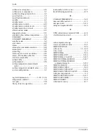
slumber mode...........................................6-12
SMART....................................................5-55
SMART comprehensive error log,
data format of .......................................5-68
SMART error logging..............................5-65
SMART self-test ......................................5-68
SMART self-test log data format.............5-69
SMART summary error log, data
format of...............................................5-66
software reset (SRST) ..............................5-28
Summary of Contents for MHV2040BH
Page 1: ...C141 E224 02EN MHV2120BH MHV2100BH MHV2080BH MHV2060BH MHV2040BH DISK DRIVES PRODUCT MANUAL ...
Page 4: ...This page is intentionally left blank ...
Page 8: ...This page is intentionally left blank ...
Page 10: ...This page is intentionally left blank ...
Page 12: ...This page is intentionally left blank ...
Page 42: ...This page is intentionally left blank ...
Page 54: ...This page is intentionally left blank ...
Page 74: ...This page is intentionally left blank ...
Page 86: ...Interface 5 12 C141 E224 Figure 5 2 Example of the circuit for driving Ready LED ...
Page 236: ...This page is intentionally left blank ...
Page 258: ...This page is intentionally left blank ...
Page 262: ...This page is intentionally left blank ...
Page 264: ...This page is intentionally left blank ...
Page 272: ...This page is intentionally left blank ...
Page 274: ......
Page 275: ......
Page 276: ......


