C141-E224
IN-1
Index
A
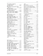
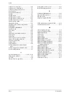
A/D converter circuit............................... 4-11
AAM...................................................... 5-109
acceleration mode.................................... 4-19
acoustic noise .......................................... 1-10
acoustic noise specification ..................... 1-10
active field ............................................... 5-28
active idle mode......................................... 6-8
active mode.......................................6-8, 6-11
actuator ...............................................2-2, 4-2
actuator motor control ............................. 4-18
adaptability ................................................ 1-2
advanced power management................. 1-13,
1-14, 5-107
AGC circuit ............................................. 4-10
air circulation system................................. 2-2
air filter ...................................................... 4-3
ambient temperature .................................. 3-6
APM .............................................1-13, 5-107
area, service ............................................... 3-7
attribute ID .............................................. 5-61
attribute value
current .................................................. 5-62
raw ....................................................... 5-62
worst case............................................. 5-62
automatic acoustic management............ 5-109
average positioning time............................ 1-2
B
BIST active - bidirectional ...................... 5-20
blower........................................................ 4-3
blower effect.............................................. 2-2
breather, location of................................... 3-5
burst even1 .............................................. 4-17
burst even2 .............................................. 4-17
burst odd .................................................. 4-17
busy (BSY) bit......................................... 5-27
C
cache
read-ahead............................................ 6-13
write ..................................................... 6-20
cache operation........................................ 6-20
cached data, invalidation of..................... 6-20
caching
command for .............................. 6-14, 6-20
data for .................................................6-14
caching data, invalidating ........................6-15
caching operation.....................................6-14
capability, off-line data collection ...........5-64
cashing function at power-on...................6-21
caution, handling........................................3-7
CHECK POWER MODE ........................5-53
checksum .............................. 5-65, 5-67, 5-69
circuit
controller ................................................2-3
read/write................................................2-3
circuit configuration........................... 4-3, 4-5
circulation filter..........................................2-2
CN1..........................................................3-10
code
command .................................. 5-29, 5-148
diagnostic .............................................5-43
command code ............................. 5-29, 5-148
command code and parameter .................5-29
command data structure ...........................5-67
command description...............................5-32
command execution, status after..............5-24
command field .........................................5-28
command for caching..................... 6-14, 6-20
command processing during
self-calibration........................................4-8
command protocol .................................5-150
DMA data-in ......................................5-155
DMA data-out ....................................5-156
native queued .....................................5-157
non-data.................................. 5-150, 5-151
PIO data-in .........................................5-152
PIO data-out .......................................5-153
command, host .........................................5-29
command, power......................................6-10
communication layer................................5-15
compact......................................................1-2
compensating open loop gain.....................4-7
COMRESET ..........................................5-160
COMRESET preservation
requirement ............................................6-5
COMRESET response .............................6-21
COMRESET sequence ..........................5-162
COMRESET, response to ..........................6-4
conceptual layer, conceptual diagram......5-14
Summary of Contents for MHV2040BH
Page 1: ...C141 E224 02EN MHV2120BH MHV2100BH MHV2080BH MHV2060BH MHV2040BH DISK DRIVES PRODUCT MANUAL ...
Page 4: ...This page is intentionally left blank ...
Page 8: ...This page is intentionally left blank ...
Page 10: ...This page is intentionally left blank ...
Page 12: ...This page is intentionally left blank ...
Page 42: ...This page is intentionally left blank ...
Page 54: ...This page is intentionally left blank ...
Page 74: ...This page is intentionally left blank ...
Page 86: ...Interface 5 12 C141 E224 Figure 5 2 Example of the circuit for driving Ready LED ...
Page 236: ...This page is intentionally left blank ...
Page 258: ...This page is intentionally left blank ...
Page 262: ...This page is intentionally left blank ...
Page 264: ...This page is intentionally left blank ...
Page 272: ...This page is intentionally left blank ...
Page 274: ......
Page 275: ......
Page 276: ......


