


Installation Conditions
3-4
C141-E224
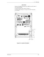
(2) Frame
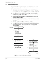
The MR head bias of the HDD disk enclosure (DE) is zero. The mounting frame
is connected to Signal Ground (SG).
IMPORTANT
Use M3 screw for the mounting screw and the screw length should
satisfy the specification in Figure 3.3.
The tightening torque must be 0.49N•m (5kgf•cm).
m (5kgf•cm).
When attaching the HDD to the system frame, do not allow the
system frame to touch parts (cover and base) other than parts to
which the HDD is attached.
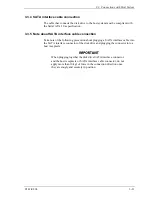
(3) Limitation of mounting
Note) These dimensions are recommended values; if it is not possible to satisfy
them, contact us.
Screw
Screw
Details of A
3.0 or less
3.0 or less
Frame of system
cabinet
Frame of system
cabinet
B
PCA
A
2
2.5
2.5
2.5
2.5
DE
Side surface
mounting
Bottom surface mounting
Figure 3.3 Mounting frame structure
Summary of Contents for MHV2040BH
Page 1: ...C141 E224 02EN MHV2120BH MHV2100BH MHV2080BH MHV2060BH MHV2040BH DISK DRIVES PRODUCT MANUAL ...
Page 4: ...This page is intentionally left blank ...
Page 8: ...This page is intentionally left blank ...
Page 10: ...This page is intentionally left blank ...
Page 12: ...This page is intentionally left blank ...
Page 42: ...This page is intentionally left blank ...
Page 54: ...This page is intentionally left blank ...
Page 74: ...This page is intentionally left blank ...
Page 86: ...Interface 5 12 C141 E224 Figure 5 2 Example of the circuit for driving Ready LED ...
Page 236: ...This page is intentionally left blank ...
Page 258: ...This page is intentionally left blank ...
Page 262: ...This page is intentionally left blank ...
Page 264: ...This page is intentionally left blank ...
Page 272: ...This page is intentionally left blank ...
Page 274: ......
Page 275: ......
Page 276: ......