


Interface
5-76
C141-E224
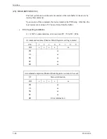
Table 5.24 DEVICE CONFIGURATION IDENTIFY data structure (2/2)
Word Value
Content
8
X ' 0015 '
Serial-ATA command set/function
→
Reflected in IDENTIFY information ”Word 76 to 79.
Bits 15-5:
Reserved
Bit 4: 1 = Software Settings Preservation supported
Bit 3:
1 = Asynchronous Notification supported
Bit 2:
1 = Interface power management supported
Bit 1:
1 = Non-zero buffer offsets in DMA Setup FIS supported
Bit 0:
1 = Native command queuing supported
9
X ' 0000 '
Reserved for Serial-ATA
10 to 254
X'0000'
Reserved
255
X'xxA5'
Bits 15-8:
Check sum code (This is obtained by calculating the sum of
all upper bytes and lower bytes in WORD 0 to 256 and the
byte consisting of bits 7 to 0 in WORD 255, and then
calculating the two's complement of the lowest byte of that
sum.)
Bits 7-0:
Summary of Contents for MHV2040BH
Page 1: ...C141 E224 02EN MHV2120BH MHV2100BH MHV2080BH MHV2060BH MHV2040BH DISK DRIVES PRODUCT MANUAL ...
Page 4: ...This page is intentionally left blank ...
Page 8: ...This page is intentionally left blank ...
Page 10: ...This page is intentionally left blank ...
Page 12: ...This page is intentionally left blank ...
Page 42: ...This page is intentionally left blank ...
Page 54: ...This page is intentionally left blank ...
Page 74: ...This page is intentionally left blank ...
Page 86: ...Interface 5 12 C141 E224 Figure 5 2 Example of the circuit for driving Ready LED ...
Page 236: ...This page is intentionally left blank ...
Page 258: ...This page is intentionally left blank ...
Page 262: ...This page is intentionally left blank ...
Page 264: ...This page is intentionally left blank ...
Page 272: ...This page is intentionally left blank ...
Page 274: ......
Page 275: ......
Page 276: ......