6.3 Power Save Controlled by Interface Power Management (IPM)
C141-E224
6-11
6.3 Power Save Controlled by Interface Power Management (IPM)
The host system can change the power consumption status of the interface by
issuing the PARTIAL or SLUMBER request to the device.
6.3.1 Power save mode of the interface
The interface power consumption states of this device can be separated into the
following three modes, including the Active mode where the device is in the
active state:
•
Active mode
•
Partial mode (shallow Interface Power Down)
•
Slumber mode (deep Interface Power Down)
*
The relationship of amount of power consumption in each mode is: Active
mode > Partial mode > Slumber mode. The following table specifies a rule
about the period in which the device must switch to Active mode from the
Interface Power Down state:
Period in which the device must switch to Active mode
Partial mode
Maximum 10
µ
s
Slumber mode
Maximum 10 ms
(1) Active mode
The interface is in the Active state and commands can be accepted.
(2) Partial mode
In this mode, (shallow) Power Save mode is set for the interface circuit.
The device switches to Partial mode when the following occurs:
•
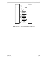
The device receives the PMREQ_P signal from the host and responds with
the PMACK signal
•
The device sends the PMREQ_S signal and the host responds with PMACK
signal.
The device cannot switch to Partial mode if the following condition is satisfied:
•
The device responds with the PMNAK signal because it is not waiting for
commands.
The device returns to Active mode from Partial mode when the following
condition is satisfied:
•
The device receives the COMRESET or COMWAKE signal from the host.
Summary of Contents for MHV2040BH
Page 1: ...C141 E224 02EN MHV2120BH MHV2100BH MHV2080BH MHV2060BH MHV2040BH DISK DRIVES PRODUCT MANUAL ...
Page 4: ...This page is intentionally left blank ...
Page 8: ...This page is intentionally left blank ...
Page 10: ...This page is intentionally left blank ...
Page 12: ...This page is intentionally left blank ...
Page 42: ...This page is intentionally left blank ...
Page 54: ...This page is intentionally left blank ...
Page 74: ...This page is intentionally left blank ...
Page 86: ...Interface 5 12 C141 E224 Figure 5 2 Example of the circuit for driving Ready LED ...
Page 236: ...This page is intentionally left blank ...
Page 258: ...This page is intentionally left blank ...
Page 262: ...This page is intentionally left blank ...
Page 264: ...This page is intentionally left blank ...
Page 272: ...This page is intentionally left blank ...
Page 274: ......
Page 275: ......
Page 276: ......

