


Interface
5-14
C141-E224
5.2 Logical Interface
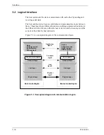
The host system and the device communicate with each other by sending and
receiving serial data.
The host and the device have several dedicated communication layers between
them. These layers have different functions, enabling communication between
the different levels of layers within the host or device and between layers at the
same level that link the host and device.
Figure 5.3 is a conceptual diagram of the communication layers.
Host:
Software control
Buffer Memory
DMA engine(s)
Host located layers
Physical Layer
Link Layer
Transport Layer
Device located layers
Physical Layer
Link Layer
Transport Layer
Device:
Software control
Buffer memory
DMA engine(s)
Application
layer 4
Transport
layer 3
Link
layer 2
Physical
layer 1
Shadow Block Register
Block Register
Figure 5.3 Conceptual diagram of communication layers
Summary of Contents for MHV2040BH
Page 1: ...C141 E224 02EN MHV2120BH MHV2100BH MHV2080BH MHV2060BH MHV2040BH DISK DRIVES PRODUCT MANUAL ...
Page 4: ...This page is intentionally left blank ...
Page 8: ...This page is intentionally left blank ...
Page 10: ...This page is intentionally left blank ...
Page 12: ...This page is intentionally left blank ...
Page 42: ...This page is intentionally left blank ...
Page 54: ...This page is intentionally left blank ...
Page 74: ...This page is intentionally left blank ...
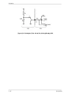
Page 86: ...Interface 5 12 C141 E224 Figure 5 2 Example of the circuit for driving Ready LED ...
Page 236: ...This page is intentionally left blank ...
Page 258: ...This page is intentionally left blank ...
Page 262: ...This page is intentionally left blank ...
Page 264: ...This page is intentionally left blank ...
Page 272: ...This page is intentionally left blank ...
Page 274: ......
Page 275: ......
Page 276: ......